
Information


Teledyne LeCroy WaveAce Integration with LogicStudio page | 7 of 10
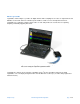
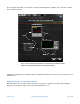
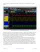
Figure 5: The initial LogicStudio screen with its large waveform display area, channel indicators (left-hand column), and
signal-display tools
The Signals Control panel, which is the multicolored column of channel designators on the left-side of the
LogicStudio GUI, provides for channel-by-channel modification of signal display. It is a simple manner to add or
subtract channels using the large “plus” and “delete” buttons at the top of the column. Existing channels can be
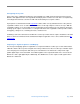
modified and/or renamed one by one by simply clicking on them, which brings up a dialog box shown in Figure 6.
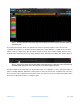
Figure 6: Clicking on any channel in the left-hand Signals Control panel brings up a dialog box in which the channel may
be modified and/or renamed. Also, this is where the source of the channel’s signal is specified
Referring to Figure 6, the channel type for channel D0 is in this case a digital line. It can be changed to numerous
options, including digital bus, digital wave, analog channel, I
2
C decode, SPI decode, or UART decode. The name
for each channel can be edited in the name field to reflect each channel’s usage. The data field designates which
line from the LogicStudio module is receiving the signal.