INSTRUCTION MANUAL D4 Digital Wireless System Fill in for your records: Serial Number: Purchase Date: Rio Rancho, NM, USA www.lectrosonics.
D4T/D4R 2 LECTROSONICS, INC.
4-channel Digital Wireless System Table of Contents Introduction..............................................................................3 General Technical Description...............................................4 D4T Transmitter......................................................................4 D4R Receiver.........................................................................5 Front and Rear Panels.............................................................6 Transmitter Input Modes........
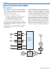
D4T/D4R General Technical Description D4T Transmitter The transmitter can accept up to four inputs from digital or analog sources. Inputs 1 and 2 are selectable between two digital channels each or 1 balanced analog channel each and inputs 3 and 4 can each accept a single balanced analog signal.
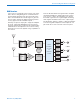
4-channel Digital Wireless System D4R Receiver The receiver is essentially a mirror image of the transmitter. The incoming RF signal is converted back into the baseband signal that was generated in the transmitter, and the FPGA decodes the signal to generate the four audio channels in digital and analog formats as they appeared at the transmitter inputs.
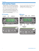
D4T/D4R Front and Rear Panels Setup and operation of the transmitter and receiver is a straightforward process using an LCD and push button interface on the front panels. The Main Window displays audio levels during operation, with a setup menu and screens to select operating modes and levels. The units are powered with an external source of 9 to 16 VDC, with power consumption of 500 mA for the transmitter and 250 mA for the receiver. The USB port is used for firmware updates.
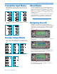
4-channel Digital Wireless System Transmitter Input Modes The transmitter can be set up in three different configurations with the AES3 mode menu for 4-channel operation: ANALOG CH 1 DIGITAL DIGITAL CH 1 DIGITAL DIGITAL CH 1 ANALOG CH 2 NOT USED CH 2 DIGITAL DIGITAL CH 2 ANALOG CH 3 ANALOG CH 3 NOT USED CH 3 ANALOG CH 4 ANALOG CH 4 NOT USED CH 4 Two different configurations are available for 2-channel operation: ANALOG CH 1 DIGITAL DIGITAL CH 1 ANALOG CH 2 NOT USED CH 2 NOT
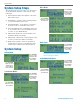
D4T/D4R System Setup Steps AES3 Modes Use UP/DOWN arrows to select menu item and press FUNC to enter setup The following steps are necessary to set up and operate the D4 system. Details for each step are on the next pages. 1) Attach antennas and power supplies to the transmitter and receiver. 2) Tuning Menu - select the same operating frequency on the transmitter and receiver.
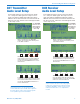
4-channel Digital Wireless System D4T Transmitter Audio Level Setup D4R Receiver Audio Level Setup Press FUNC and then select the menu item “Audio Lev. “ and press FUNC again. The setup screen for audio level will vary slightly depending upon which AES3 mode has been selected. If the 2-channel mode has been selected, channels 3 and 4 will appear blank on the setup screen. Press FUNC and then select the menu item “Audio Lev. “ and press FUNC again.
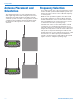
D4T/D4R Antenna Placement and Orientation The supplied antenna is a center fed half-wave type with a right angle elbow and rotating mount. For most applications, the whip antennas should be vertically oriented to provide a circular coverage pattern. In other orientations, the transmitter antenna should be parallel with and not directly above or below the receiver antennas. Frequency Selection For a single system, any of the four frequencies can be used for normal operation.
4-channel Digital Wireless System Replacement Parts and Accessories Power Supply Lectrosonics PS70 (non-locking) AC power supply with 60320 universal socket on housing, 100-240 VAC, 50/60 Hz, 1.6 A (max) input; 13.8 VDC, 2.8A, 40 W (max) output. Specify the AC power cord needed for your country or application. Power Input Plug and Cables • Shogyo MP121CR locking plug (no cable) • Lectrosonics 21425 straight, non-locking plug with 6 ft.
D4T/D4R Specifications Overall System Operating Spectrum: Center frequencies (MHz): Modulation Type: Sampling Rate: Latency (overall system): Digital In/Digital Out: Analog In/Analog Out: Selectable Audio Channels: Audio Performance (overall system): Frequency Response: THD: 12 D4T Transmitter 902 - 928 MHz 907.776, 912.387, 916.992, 921.600 Four systems can operate simultaneously for a total of 16 audio channels. QPSK with spreading to 4.2 MHz 48 kHz Less than 1 mS 2.
4-channel Digital Wireless System FCC Notice NOTE: This equipment has been tested and found to comply with the limits for a Class B digital device, pursuant to Part 15 of the FCC Rules. These limits are designed to provide reasonable protection against harmful interference in a residential installation. The equipment generates, uses and can radiate radio frequency energy and, if not installed and used in accordance with the instructions, may cause harmful interference to radio communications.
D4T/D4R Service and Repair If your system malfunctions, you should attempt to correct or isolate the trouble before concluding that the equipment needs repair. Make sure you have followed the setup procedure and operating instructions. Check the interconnecting cables and then go through the Troubleshooting section in this manual. We strongly recommend that you do not try to repair the equipment yourself and do not have the local repair shop attempt anything other than the simplest repair.
LIMITED ONE YEAR WARRANTY The equipment is warranted for one year from date of purchase against defects in materials or workmanship provided it was purchased from an authorized dealer. This warranty does not cover equipment which has been abused or damaged by careless handling or shipping. This warranty does not apply to used or demonstrator equipment. Should any defect develop, Lectrosonics, Inc. will, at our option, repair or replace any defective parts without charge for either parts or labor.