
User's Manual
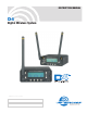


4-channel Digital Wireless System
Rio Rancho, NM, USA
3
Introduction
The D4 digital 4-channel wireless system was de-
signed as a special purpose system for location pro-
duction in film and television.
A typical application for this system is in television
production as part of what is commonly called a “bag
system.” A portable mixer and several wireless mi-
crophone receivers are carried in an over-shoulder
carrying case. The D4T transmitter is connected to the
outputs of the mixer to transmit up to four audio chan-
nels to one or more D4R receivers mounted on video
cameras.
The system is designed for line level analog audio sig-
nals and AES/EBU digital audio signals and can be set
up as a 2-channel or 4-channel system with options
that provide:
• Digitalin/Digitalout(<1mSlatency)
• Digitalin/Analogout
• Analogin/Digitalout
• Analogin/Analogout(2.2mSlatency)
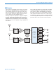
In the 4-channel mode, the D4 system operates on
one of four 4.2 MHz channels in the 902 to 928 MHz
band. Each channel carries four separate audio sig-
nals, digitally multiplexed within a common carrier. D4
systems can be run simultaneously on all four chan-
nels across the 902 to 928 MHz band to provide a total
of16channels.
907.776 912.384 916.992 921.600
902 to 928 MHz Band
Center frequencies of the RF channels
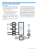
A “spreading” technique is used in the design to in-
crease immunity to noise and interference. The sam-
pled audio signals are delivered to the FPGA where
the spreading algorithm and encoding are applied.
The audio quality is suitable for any professional appli-
cation in film, television and live sound. 48 kHz sam-
pling and 24-bit A-D conversion assure excellent audio
quality across a 20Hz to 20kHz audio bandwidth with
only 0.05% distortion.
The LCD interface on the front panels make setup
simple and straightforward. Power is provided by exter-
nalsourcesfrom6to16VDC.
Rugged machined aluminum housings are finished
in a Teflon impregnated nickle alloy plating with laser
etched nomenclature for durability and legibility.
Table of Contents
Introduction .............................................................................3
General Technical Description ..............................................4
D4T Transmitter .....................................................................4
D4R Receiver ........................................................................5
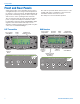
Front and Rear Panels ............................................................6
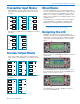
Transmitter Input Modes ........................................................7
Receiver Output Modes .........................................................7
Mixed Modes ...........................................................................7
Navigating the LCD ................................................................7
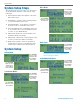
System Setup Steps ...............................................................8
System Setup ..........................................................................8
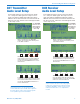
D4T Transmitter Audio Level Setup ......................................9
D4R Receiver Audio Level Setup ..........................................9
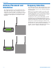
Antenna Placement and Orientation ...................................10
Frequency Selection ............................................................10
Replacement Parts and Accessories ..................................11
Specifications .......................................................................12
Service and Repair ...............................................................14
Returning Units for Repair ..................................................14