
User's Manual


D4T/D4R
LECTROSONICS, INC.
4
General Technical Description
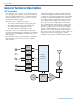
D4T Transmitter
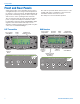
The transmitter can accept up to four inputs from digi-
taloranalogsources.Inputs1and2areselectablebe-
tweentwodigitalchannelseachor1balancedanalog
channel each and inputs 3 and 4 can each accept a
single balanced analog signal.
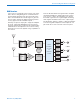
The inputs can be configured as follows:
• Fourbalancedanaloginputsusingallfourjacks
• Twodigitalchannelsusingjack1andtwobal-
ancedanaloginputsusingjacks3and4
• Fourdigitalchannelsusingjacks1and2
The input connectors are TA3 “mini XLR” types with
the same pin numbering and configuration as standard
XLR connectors for AES-EBU and balanced line level
analog signals.
Input preamp circuits use a special balanced amplifier
withveryhighcommonmoderejectiontominimize
hum and noise.
Analog input signals are sampled at 48kHz and con-
verted to 24-bit digital audio and fed into the FPGA
for further processing. The FPGA applies a spreading
algorithm to expand the bandwidth of each channel
to 4,2 MHz to improve immunity to interference and
noise. The baseband signal is then delivered to the
D-A to generate the I and Q signals for final output.
The modulated signal is filtered before and after the
RF amp to suppress out of band noise and spurious
signals. A circulator/isolator is used in the final RF
output to minimize IM that can occur when external
signals enter the output stage through the antenna.
The isolator passes the transmitter output signal to the
antenna but shunts returning signals to ground.
A USB port is provided to simplify firmware updates.
POWER
AMP
OSC
900 MHz
RF
DEMOD
DIGITAL
BASEBAND
ENCODER
24-bit D/A
(analog)
AES/EBU
OUT
(digital)
24-bit D/A
(analog)
AES/EBU
OUT
(digital)
24-bit D/A
(analog)
24-bit D/A
(analog)
TA3F
INPUTS
CIRCULATOR
ISOLATOR
FILTER
1
2
3
4