
User's Manual


4-channel Digital Wireless System
Rio Rancho, NM, USA
5
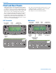
D4R Receiver
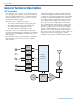
The receiver is essentially a mirror image of the trans-
mitter. The incoming RF signal is converted back into
the baseband signal that was generated in the trans-
mitter, and the FPGA decodes the signal to generate
the four audio channels in digital and analog formats
as they appeared at the transmitter inputs.
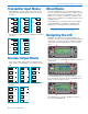
Diversity reception is employed to suppress multipath
dropouts, followed by SAW filters in the front-end to
attenuate signals above and below the passband. The
FPGAmonitorsandadjuststheleveloftheincoming
RF signal to increase the dynamic range capabilities of
the receiver.
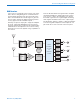
From the IQ demodulator through the filters, amplifier
and baseband ADC, the signal path and processing
is the reverse of that in the transmitter. Decoding in
the FPGA regenerates the original digital and analog
audio signals and delivers them to the output stages.
The FPGA also delivers a signal to a DAC and amplifer
for monitoring with headphones. The headphone out-
put follows the receiver selected on the front panel.
FILTER
FILTER
LOW
NOISE
AMP
LOW
NOISE
AMP
OSC
900 MHz
RF
DEMOD
RF
DEMOD
DIGITAL
BASEBAND
DECODER
and
DIVERSITY
SYSTEM
24-bit D/A
(analog)
AES/EBU
OUT
(digital)
24-bit D/A
(analog)
AES/EBU
OUT
(digital)
24-bit D/A
(analog)
24-bit D/A
(analog)
TA3F
OUTPUTS
1
2
3
4