
User's Manual


D4T/D4R
LECTROSONICS, INC.
6
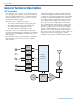
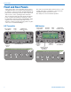
Front and Rear Panels
Setup and operation of the transmitter and receiver is
a straightforward process using an LCD and push but-
ton interface on the front panels. The Main Window dis-
plays audio levels during operation, with a setup menu
and screens to select operating modes and levels.
The rear panels provide the audio inputs and outputs,
powerreceptacleandUSBport.Channels1and2
provide balanced analog signals and AES-EBU digital
signals as selected from the LCD setup screens.
Channels 3 and 4 are balanced analog audio only. The
connectors are standard TA3M type.
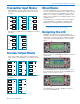
D4T Transmitter
FUNC
BACK
OFF
ON
1
2
34
DIGITAL 4 CHANNEL TRANSMITTER
Channel Select 1-4
Menu Item &
Parameter Select
Return to
Previous
Menu
Press to Enter
Setup Menus
Audio
Level
USBAES 3/4
1
2
3
4
9-16 VDC
500 mA
AES 1/2
D4T 4-CHANNEL DIGITAL TRANSMITTER
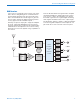
The units are powered with an external source of 9 to
16VDC,withpowerconsumptionof500mAforthe
transmitter and 250 mA for the receiver.
The USB port is used for firmware updates.
D4R Receiver
FUNC
BACK
OFF
ON
1
2
3
4
PHONES
DIGITAL 4 CHANNEL RECEIVER
Channel
Select 1-4
Menu Item/Parameter
Select Buttons
Press to Enter
Setup Menus
Return to
Previous
Menu
Channel selected
for headphone
monitoring
Incoming
RF level
Menu Item &
Parameter Select
Audio
Level
USBAES 3/4
1
2
3
4
9-16 VDC
300 mA
AES 1/2
D4R 4-CHANNEL DIGITAL RECEIVER