
User's Manual


DBu, DBu/E01
LECTROSONICS, INC.
2
Introduction
The DBu, DBu/E01 transmitter employs high efficiency
digital circuitry for extended operating time on two AA
batteries. The transmitter can tune in coarse or fine
steps across the UHF television band from 470.100 to
607.950 MHz (DBu/E01 frequency range is 470.100 to
614.375 MHz), with a selectable output power of 25 or
50 mW. The pure digital architecture enables AES 256-
CTR encryption for high level security applications.
Studio quality audio performance is assured by high
quality components in the preamp, wide range input
gain adjustment and DSP-controlled limiting. Input
connections and settings are included for any lavaliere
microphone, dynamic microphones and line level inputs.
Input gain is adjustable over a 44 dB range in 1 dB
steps to allow an exact match to the input signal level,
to maximize the dynamic range and signal to noise
ratio.
Frequency Agility
The transmitter tunes across the entire frequency
range, from 470.100 MHz to 607.950 MHz (DBu/E01
frequency range is 470.100 to 614.375 MHz).
Encryption
When transmitting audio, there are situations where
privacy is essential, such as during professional sport-
ing events, in court rooms or private meetings. For
instances where your audio transmission needs to be
kept secure, without sacrificing audio quality, Lectroson-
ics introduces Encryption Keys. Truly entropic encryp-
tion keys are first created by a Lectrosonics receiver,
such as the DSQD Receiver. The key is then synced
with the DBu, DBu/E01 via the IR port. The audio will
be encrypted and can only be listened to if both DBu,
DBu/E01and receiver have the matching encryption key.
If you are trying to transmit an audio signal and keys
do not match, all that will be heard is silence or white
noise.
Table of Contents
Introduction ............................................................................ 2
Frequency Agility.................................................................. 2
Encryption ............................................................................ 2
Servo Bias Input and Wiring ................................................ 3
DSP-controlled Input Limiter ................................................ 3
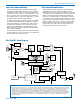
DBu, DBu/E01 Block Diagram ............................................. 3
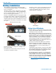
Battery Installation ................................................................ 4
Battery Status LED Indicator ............................................... 4
Belt Clips .............................................................................. 5
IR (infrared) Port .................................................................. 5
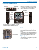
Features and Functions ........................................................ 5
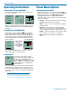
Operating Instructions .......................................................... 6
Powering On in Operating Mode .......................................... 6
Powering On in Standby Mode ............................................ 6
Powering Off ........................................................................ 6
Power Menu Options ............................................................. 6
Entering the Power Menu ..................................................... 6
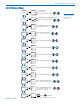
LCD Menu Map ....................................................................... 7
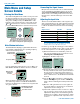
Main Menu and Setup Screen Details .................................. 8
Entering the Main Menu ....................................................... 8
Main Window Indicators ...................................................... 8
Connecting the Signal Source ............................................. 8
Adjusting the Input Gain ....................................................... 8
Selecting Frequency ............................................................ 9
Selecting Programmable Switch Functions.......................... 9
Selecting the Low Frequency Roll-off .................................. 9
Selecting Audio Polarity (Phase) .......................................... 9
Selecting Battery Type ......................................................... 9
Setting Transmitter Output Power ........................................ 9
Remote ................................................................................ 9
Locking/Unlocking Changes to Settings............................... 10
Restoring Default Settings ................................................... 10
KeyType ............................................................................... 10
WipeKey ............................................................................... 10
SendKey ............................................................................... 10
LectroRM ................................................................................ 11
Whip Antennas ..................................................................... 12
Encryption Key and Settings Transfer ................................ 12
Accessories ........................................................................... 13
5-Pin Input Jack Wiring ......................................................... 14
Microphone Cable Termination
for Non-Lectrosonics Microphones .............................. 15
Input Jack Wiring for Different Sources .............................. 16
Microphone RF Bypassing ................................................... 17
Line Level Signals ................................................................ 17
Wireless Designer Software ................................................ 18
Firmware Update Instructions .............................................. 18
Specifications ........................................................................ 19
Troubleshooting ..................................................................... 20
Service and Repair ................................................................ 21
Returning Units for Repair ................................................... 21