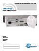
HARDWARE and SOFTWARE INSTALLATION GUIDE DM Series Digital Audio Processors Models: DM1624F DM1612F DM812 Fill in for your records: Serial Number: Purchase Date: Rio Rancho, NM, USA www.lectrosonics.
DM Series Installation Guide 2 LECTROSONICS, INC.
DM Series Installation Guide Important Safety Instructions This symbol, wherever it appears, alerts you to the presence of uninsulated dangerous voltage inside the enclosure -- voltage that may be sufficient to constitute a risk of shock. This symbol, wherever it appears, alerts you to important operating and maintenance instructions in the accompanying literature. Please read the manual. 1) Read these instructions. 2) Keep these instructions. 3) Heed all warnings. 4) Follow all instructions.
DM Series Installation Guide Table of Contents Important Safety Instructions................................................ 3 Introduction.............................................................................. 5 Unpacking the Unit................................................................. 5 Items Included in the Box:...................................................... 5 Hardware Installation..............................................................
DM Series Installation Guide Introduction The purpose of this guide is to assist in the setup and operation of a typical DM system. This guide assumes familiarity with the DM Series Digital Audio Processors, its components and software menus and setup screens. To get the most out of the DM system, it is suggested to review the information presented in the DM Series Reference Manual.
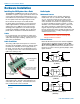
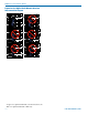
DM Series Installation Guide Hardware Installation Installing the DM System into a Rack The DM1624F and DM1612F occupy two rack spaces. The DM812 occupies a single space. Mount with 4 rack screws using the appropriate mounting holes. It is recommended to use nylon washers to prevent damage to the front panel’s finish when tightening the screws. Do not obstruct the fan port on the 2RU models.
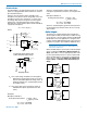
DM Series Installation Guide Phantom Power The DM supplies +15 VDC phantom power to the audio inputs via a programmable switch and two 2 k resistors. (See illustration below.) Since the calculated Vph is equal to Vph from the microphone specification sheet, this is a marginal situation. However, the true phantom power available at the microphone may be less due to voltage drop across the microphone itself (source resistance).
DM Series Installation Guide Programmable Inputs Programmable inputs are provided to enable external control over a variety of parameters. Each input can respond to either a contact closure or a continuous voltage. The following illustrates common connections to the programmable input pins. (See also Programmable Inputs and Outputs Wiring Diagram.
DM Series Installation Guide WARNING: The Expansion I/O connectors are NOT EtherNet, CobraNet or any other network based device interconnects. Connecting them to Ethernet, CobraNet or other network based device may cause damage to either unit.
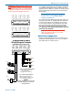
DM Series Installation Guide Expansion Port Digital Audio Network Interface Interconnection Diagram 1 - GND 2 - IN 12 3 - IN 14 4 - IN 16 5 - IN 18 6 - IN 20 7 - IN 22 8 - GND 9 - OUT 9 10 - OUT 11 11- OUT 13 12 - OUT 15 13 - GND 14 - +5V 15 - IN 13 16 - IN 15 17 - IN 17 18 - IN 19 19 - IN 21 20 - +5V 21 - OUT 10 22 - OUT 12 23 - OUT 14 24 - OUT 16 25 - +5V PROGRAMMABLE INPUTS/ OUTPUTS 1 - GND 2 - IN 1 3 - IN 3 4 - IN 5 5 - IN 7 1 - GND 2 - IN 12 3 - IN 14 4 - IN 16 5 - IN 18 6 - IN 9 7 - IN 11 8 -
DM Series Installation Guide Control System Interconnections Part# 21529-1 (Black Cable) In addition to a Windows® based computer system, DM processors can be controlled by external serial control system using the RS-232 interface, such as those from Crestron® and AMX®.* Device to PC S R T 9 or 25 Pin Female D-Subminiature 3.
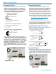
DM Series Installation Guide Installing LecNet2™ Software and USB Driver The LecNet2 USB drivers are installed from the Installation Disk which comes with each processor by running the LecNet2 Device Installer. Normally, this is done before connecting a processor for the first time, however, it can done afterwards if necessary. The driver installation only needs to be done once.
DM Series Installation Guide The drivers are installed from the CD. When installation is complete, the final page of the installer will appear. The Driver Name and Status are displayed. Click on Finish to close the installer. You may new connect any LecNet2 device to the PC and drivers will be loaded automatically. Manual Installation If the USB drivers have not been pre-installed on a PC prior to connecting a LecNet2 device for the very first time, you may install the manually if you wish.
DM Series Installation Guide Initial Setup The initial setup of a DM system is a relatively simple three step process: connect the unit to the computer, turn on the computer and select the appropriate control panel, preset the input, matrix and output. This process assumes that LecNet2™ and, if necessary, the USB driver have been previously installed. If they have not been installed, please refer to Installing LecNet2™ Software and USB Driver.
DM Series Installation Guide Inputs Matrix Outputs 6) Help is always available by clicking Help on the Main Menu Bar. This Help is a comprehensive resource and includes the latest revisions to the software and firmware. IMPORTANT: ANY CHANGES MADE DURING SETUP MUST BE SAVED IN THE UNIT VIA THE PRESET MENU. For direct support from the factory, call 1-800-821-1121 Ask for anyone in the SALES department.
LIMITED ONE YEAR WARRANTY The equipment is warranted for one year from date of purchase against defects in materials or workmanship provided it was purchased from an authorized dealer. This warranty does not cover equipment which has been abused or damaged by careless handling or shipping. This warranty does not apply to used or demonstrator equipment. Should any defect develop, Lectrosonics, Inc. will, at our option, repair or replace any defective parts without charge for either parts or labor.