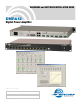
HARDWARE and SOFTWARE INSTALLATION GUIDE DMPA12 Digital Power Amplifier Fill in for your records: Serial Number: Purchase Date: Rio Rancho, NM, USA www.lectrosonics.
DMPA12 Installation Guide 2 LECTROSONICS, INC.
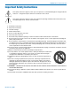
DMPA12 Installation Guide Important Safety Instructions This symbol, wherever it appears, alerts you to the presence of uninsulated dangerous voltage inside the enclosure -- voltage that may be sufficient to constitute a risk of shock. This symbol, wherever it appears, alerts you to important operating and maintenance instructions in the accompanying literature. Please read the manual. 1) Read these instructions. 2) Keep these instructions. 3) Heed all warnings. 4) Follow all instructions.
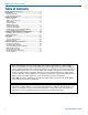
DMPA12 Installation Guide Table of Contents Important Safety Instructions................................................ 3 Introduction.............................................................................. 5 Unpacking the Unit................................................................. 5 Items Included in the box:...................................................... 5 Hardware Installation.............................................................. 6 Rack Installation......................
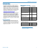
DMPA12 Installation Guide Introduction The purpose of this guide is to assist in the correct installation and initial setup of a DMPA12 digital power amplifier in a sound system utilizing other DM Series components. This guide assumes familiarity with the DMPA12 amplifier and other components and software used in the system.
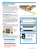
DMPA12 Installation Guide Hardware Installation Rack Installation The DMPA12 occupies a single rack space and there are no special ventilation requirements. Mount with 4 rack screws through the ears on the front panel.It is recommended to use nylon washers to prevent damage to the front panel’s finish when tightening the screws. While it is not mandatory, it is good practice to leave an empty rack space above the amplifier. The amplifier should be mounted in a rack with rear support rails.
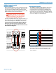
DMPA12 Installation Guide DANI Bus (expansion ports) Expansion I/O ports The four RJ45 connectors on the rear panel are used to interconnect LecNet2™ units together. These ports are only used to transfer digital audio information via the Digital Audio Network Interface (DANI) between the DM Series processors that are interconnected. WARNING: The Expansion I/O connectors are NOT EtherNet, CobraNet or any other network based device interconnects.
DMPA12 Installation Guide DMPA12 Rear Panel TX 1 14 13 25 1: GND 2: IN 1 3: IN 3 4: IN 5 5: IN 7 6: IN 9 7: IN 11 8: GND 9: OUT 1 10: OUT 3 11: OUT 5 12: OUT 7 13: GND 14: +5V 15: IN 2 16: IN 4 17: IN 6 18: IN 8 19: IN 10 20: +5V Programmable inputs are provided to enable external control over a variety of parameters. Each input can respond to either a contact closure or a continuous voltage. The following illustrates common connections to the programmable input pins.
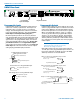
DMPA12 Installation Guide Programmable Inputs and Outputs Wiring Remote control with external pots and switches is provided with Programmable Inputs on a standard DB-25 connector on the rear panel. Programmable Outputs are used to provide external LED indicators and to trigger other events. Examples of the wiring are shown below.
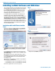
DMPA12 Installation Guide Installing LecNet2 Software and USB Driver The LecNet2 USB drivers are installed from the Installation Disk which comes with each processor by running the LecNet2 Device Installer. Normally, this is done before connecting a processor for the first time, however, it can done afterwards if necessary. The driver installation only needs to be done once.
DMPA12 Installation Guide Manual Installation If the USB drivers have not been pre-installed on a PC prior to connecting a LecNet2 device for the very first time, you may install the manually if you wish. On Windows XP and Vista operating systems, the Found New Hardware Wizard will open when the device is detected. It will walk you through the process of installing the LecNet2 drivers. To proceed, you will need the LecNet2 Installation Disk.
DMPA12 Installation Guide Control System Interconnections Part# 21529-1 (Black Cable) In addition to a Windows based computer system, the DM84 can be controlled by external serial control system using the RS-232 interface, such as those from Crestron® and AMX®.
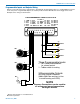
DMPA12 Installation Guide Initial Setup Connect The initial setup of a DMPA12 system is a simple four step process: • Set the unit to the Master mode, if necessary • Connect the unit to the computer For simplicity, the instructions shown on this page include only USB and RS-232 connections for setup using a computer connected directly to the amplier. For additional methods of connecting to the unit including network and offline use, see page 17.
DMPA12 Installation Guide Select the Signal Source The input signal to the amplifier is taken from the DANI (digital audio network interface) or from a tone or pink noise source generated in the amplifier. It is useful to use the tone or pink noise source during initial setup to verify proper connections and signal routing to the loudspeakers. With a DM processor installed and microphones or other audio sources are available, the sound system can be operated during setup.
DMPA12 Installation Guide Adjust the Gain / Level The default setting on the amplifier is OFF, so no signal will be passed to the outputs until a value is selected. Values can be entered directly into the field, or the values can be scrolled up and down with mouse clicks. The multi-colored bar graphs indicate the signal levels at the outputs. The LEDs indicate yellow for compression and red for limiting. Initial Setup Hints 1) The GUI interface is quite intuitive.
DMPA12 Installation Guide Additional Settings and Functions In many cases the installer is required to make additional settings and/or adjustments to enable functions such as auxiliary remote controls using pots and switches. Since some of these additional functions affect the basic signal flow and levels, it is important for the installer to understand what is available and how some of the most important processes work.
DMPA12 Installation Guide Front Panel Output Activity Indicators These indicators reflect activity on the output audio channels.
DMPA12 Installation Guide Connect Options The DMPA12 can be connected to a computer via the following methods: USB - A standard interface that launches automatically when the unit is connected and turned on. Front and rear USB ports are provided. RS-232 - For direct computer connecton with this standard serial interface, or for use with a Crestron® or AMX® control system.
DMPA12 Installation Guide Rio Rancho, NM 19
LIMITED ONE YEAR WARRANTY The equipment is warranted for one year from date of purchase against defects in materials or workmanship provided it was purchased from an authorized dealer. This warranty does not cover equipment which has been abused or damaged by careless handling or shipping. This warranty does not apply to used or demonstrator equipment. Should any defect develop, Lectrosonics, Inc. will, at our option, repair or replace any defective parts without charge for either parts or labor.