INSTALLATION and QUICK START GUIDE DMTH4 Digital Telephone Hybrid Fill in for your records: Serial Number: Purchase Date: Rio Rancho, NM, USA www.lectrosonics.
DMTH4 2 LECTROSONICS, INC.
Installation Guide Important Safety Instructions This symbol, wherever it appears, alerts you to the presence of uninsulated dangerous voltage inside the enclosure -- voltage that may be sufficient to constitute a risk of shock. This symbol, wherever it appears, alerts you to important operating and maintenance instructions in the accompanying literature. Please read the manual.
DMTH4 Table of Contents Important Safety Instructions................................................ 3 Introduction.............................................................................. 5 Unpacking the unit................................................................. 5 Controls and Features............................................................ 6 Front Panel............................................................................. 6 Rear Panel...........................................
Installation Guide Introduction The purpose of this guide is to assist in the setup and operation of a typical DMTH4 system. This guide assumes familiarity with the DM Series Digital Audio Processors, its components and software menus and setup screens. To get the most out of the DMTH4 system, it is suggested to review the information presented in the DMTH4 Series Reference Manual.
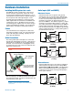
DMTH4 Controls and Features Front Panel R TELEPHONE HYBRID INTERFACE MODE STATUS Mode Switch USB Status LED POWER On/Off Switch POWER USB Port POWER On/Off Switch Note: The DMTH4 is shipped from the factory configured as a Master unit. In this mode, the Status indicator glows steadily when power is applied. The Power On/Off Switch is used to turn the DMTH4 on (1) or off (0).
Installation Guide Hardware Installation Installing the DM system into a rack The DMTH4 occupies a single space. There are no special ventilation requirements. Mount with 4 rack screws using the appropriate mounting holes. It is recommended to use nylon washers to prevent damage to the front panel’s finish when tightening the screws. For North American installations, connect the Power Cable supplied with the unit between the DMTH4 and a stable power source.
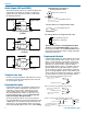
DMTH4 Potentiometer Connection for Analog Control of Gain Audio Outputs (AUX and CODEC) The AUX and Codec outputs are a balanced differential configuration and include an attenuator to reduce the signal to mic level. Wire these outputs as indicated in the following illustration.
Installation Guide Note: The diagram shows an external DC source powering the relay coil. This is necessary whenever coil voltages exceed 5 V. Both LEDs and 5V relay coils can be powered by the +5 V DC pins on the programmable input connector, as long as the maximum combined current for all LEDS and relay coils does not exceed 100 mA.
DMTH4 Control System Interconnections Part# 21529-1 (Black Cable) In addition to a Windows® based computer system, the DM84 can be controlled by external serial control system using the RS-232 interface, such as those from Crestron® and AMX®.
Installation Guide Installing LecNet2™ Software and USB Driver The LecNet2 USB drivers are installed from the Installation Disk which comes with each processor by running the LecNet2 Device Installer. Normally, this is done before connecting a processor for the first time, however, it can done afterwards if necessary. The driver installation only needs to be done once. Click on the option that is correct for your PC.
DMTH4 Accept, then click Next to proceed. Manual Installation If the USB drivers have not been pre-installed on a PC prior to connecting a LecNet2 device for the very first time, you may install the manually if you wish. On Windows XP and Vista operating systems, the Found New Hardware Wizard will open when the device is detected. It will walk you through the process of installing the LecNet2 drivers. To proceed, you will need the LecNet2 Installation Disk.
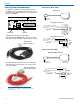
Installation Guide Basic System Setup Control System Interconnections In addition to a Windows® 2000 or XP based computer system, DMTH4s can be controlled by external serial control system using the RS-232 interface, such as those from Crestron® and AMX®. Two RS-232 cables are provided. They are identified by the color of the cable. The black cable is used to connect a computer system to the DMTH4 and the red cable is used to connect a serial control system such as those from Crestron® or AMX®.
DMTH4 Network - One or more DMTH4 devices may be made available for network connections by connecting them to a gateway computer system. A gateway PC, or gateway server acts as a middleman, receiving commands for a DMTH4 over a network connection, and forwarding them to the DMTH4, which is connected to it via USB. To work as a gateway server the PC must be a member of some local area network (LAN) or the internet, by means of an Ethernet connection, and be running the Lecnet2 “Net Server” program.
Installation Guide WIth the DMTH4 connection configured, it is now possible to set the Master/Slave operating mode. This is done by selecting “Device Setup” from the Control Panel Menu Bar. Select “Expansion Mode” from the drop down menu and select “Slave.” Initial Setup Hints 1) Right clicking the mouse is powerful in this interface. You can activate quick access to a number of setup functions (for example - right click in any input box in the INPUTS tab).
DMTH4 Example Teleconferencing Setup Link Conference Rooms with a DMTH4 Example Setup The following information describes setting up a DMTH4 to connect two locations for a conference. The DMTH4 is designed to be part of a DM Series chain. In this example, the DMTH4 is a slave unit to a DM1624 Series Automixer. This example also assumes that the hardware has been installed and is operating properly.
Installation Guide The following are assumed: • A POTS line has already been connected to the DMTH4 rear panel Telephone Line jack • The DMTH4 has been connected to the DM1624 via the DANI bus • The microphones and overhead speakers are already connected to the DM1624 in a Mix-Minus configuration. audio and audio from Conference Room 2 are heard on the speakers in Conference Room 1. (See Conference Room Signal Flow Diagram.) 1.
DMTH4 Inputs to Expansion Outputs Tab Connect Input Channels 1 and 2 to Expansion Out Channel 1 Setting up the DMTH4 Output Source Multiplexer The TEL output needs to be configured so that Expansion Final Mix 1 is sent over the telephone line for use at the remote Conference Room. 1.) Select the Out Source Tab in the DMTH4 Control Panel. 2.) Click the down arrow on the TEL Output Source selection list and select Exp Final Mix 1 from the list. Out Source Tab TEL Output Source 18 LECTROSONICS, INC.
Installation Guide Basic System Operation The following procedures are designed to aquaint the user of the basic steps required to set up a DMTH4 and provide a foundation for developing more complex operations. It is assumed that the LecNet2™ software and drivers have been previously installed, a Windows-based computer system is connected to the USB or RS-232 ports and the DMTH4 Control Panel is open on the computer screen.
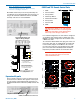
DMTH4 Use the “Type the number to dial” box 1.) Click the “Type the number to dial” box, then use the computer keyboard to enter the telephone number. When finished, click “Dial” to connect the telephone interface and dial the number. Connect 3.) To terminate the telephone call, click the “Disconnect” button on the Activities tab. Connect LED Telephone Book “Type in Number to Dial” Box Dial 2.) To terminate the telephone call, click the “Disconnect” button on the Activities tab.
Installation Guide When an incoming call is received the Ringing LED (on both the Tel/Codec Tab and the Activities Tab) will blink until the number of rings has been achieved, then extinguish to indicate that the Telephone Interface has connected. 4.) Click “Enable Auto Disconnect” to configure the DMTH4 so that the telephone interface automatically disconnects when it senses that the call has be terminated by the calling party.
DMTH4 FCC Part 68 Compliance This equipment complies with Part 68 of the FCC rules. On the rear panel of this equipment is a label that contains, among other information, the FCC registration number and ringer equivalence number (REN) for this equipment. If requested, this information must be provided to the telephone company. The telephone company may make changes in its facilities, equipment, operations, or procedures that could affect the operation of the equipment.
Installation Guide Rio Rancho, NM 23
LIMITED ONE YEAR WARRANTY The equipment is warranted for one year from date of purchase against defects in materials or workmanship provided it was purchased from an authorized dealer. This warranty does not cover equipment which has been abused or damaged by careless handling or shipping. This warranty does not apply to used or demonstrator equipment. Should any defect develop, Lectrosonics, Inc. will, at our option, repair or replace any defective parts without charge for either parts or labor.