H175DC Plug-On Transmitter OPERATING INSTRUCTIONS and trouble-shooting guide Digital Code Squelch LECTROSONICS, INC.
This page intentionally blank.
Plug-On Transmitter INTRODUCTION Thank you for selecting the Lectrosonics Professional Series wireless microphone system. This system represents well over 20 years of manufacturing experience in wireless microphones, and almost 70 years of design experience. It is the best value avail able today. You will find that the H175DC radiates more power than other standard handheld wireless microphones. This provides both greater operational range, as well as improved signal-to-noise ratio.
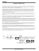
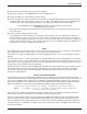
GENERAL DESCRIPTION The H175DC is a “plug-on” transmitter that converts any microphone with an XLR connector to wireless operation. The transmitter is comprised of four major functional subsystems: the mic preamp/gain control, the compandor, the compressor/limiter and the RF transmitter (see block diagram below). The digital code system provides much more reliable control over the receiver audio output than a conventional squelch can provide.
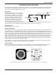
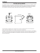
Plug-On Transmitter CONTROLS AND FUNCTIONS The H175DC may be used with a wide variety of microphones. The 3-pin XLR type connector on the H175DC allows the transmitter to be used with any dynamic microphone, as well as many two wire positive bias lavalier systems (such as those systems supplied by Lectrosonics.) INPUT JACK TO MIC PREAMP Standard 3-pin XLR type. Pin 2 is signal, pin 980 1K 1K 3 is signal ground, and pin 1 is case ground 1 UH +9 VOLTS (see schematic in Figure 2.
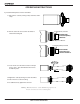
OPERATING INSTRUCTIONS 1) Install the Microphone onto the transmitter. a. Unscrew the collar by turning it fully clockwise until it stops. b. Turn the collar two turns counter-clockwise to extend the locking tab Locking tab fully retracted Knurled knob turned completely clockwise. Compression Washer Locking tab partially extended Knurled knob turned two turns counter-clockwise. Click! c. Press the mic onto the XLR connector until you hear a “click.” The click indicates the mic has locked into place.
Plug-On Transmitter 2) Turn on the receiver and adjust the output level to minimum. 3) Turn on the transmitter. The CODE LED on the receiver should come on. 4) Hold the microphone as you will when you will be using it. 5) Speak as loudly as you expect to speak in normal system use. Adjust the MIC LEVEL on the transmitter so that the LEVEL LED on the receiver flickers or stays lit as you speak. The LIMIT LED on the receiver should light up on loud “peaks.
BATTERY REPLACEMENT The H175DC transmitter is powered by a standard alkaline 9 Volt battery. It is important that you use ONLY an ALKA LINE battery for longest life. Standard zinc-carbon batteries marked “heavy duty” or “long-lasting” are not adequate. They will provide only about 4 hours of operation. Similarly, nicad rechargeable batteries only give 4 hours of opera tion, and will also run down quite abruptly. Alkaline batteries provide about 12 to 14 hours of operation.
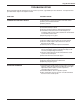
Plug-On Transmitter TROUBLESHOOTING Before going through the following chart, be sure that you have a good battery in the transmitter. It is important that you follow these steps in the sequence listed. SYMPTOM POSSIBLE CAUSE TRANSMITTER BATTERY LED OFF 1) Unit turned off. Check front panel on/off slide switch. 2) Battery is inserted backwards. 3) Battery is dead. RECEIVER RF OR CODE LAMP OFF 1) Transmitter not turned on. 2) Transmitter battery is dead.
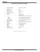
SPECIFICATIONS AND FEATURES Operating frequencies: 169 to 172 MHz; 174 to 186 MHz RF Power output: 50mW Deviation: ±15kHz Spurious radiation: 55dB below carrier Equivalent input noise: -121dBV Input Types: 200 Ohm dynamic 5V phantom power 1k Ohm, 2-wire electret with 5 VDC positive bias Level: Nominal 2mV to 300mV (before compression) Impedance: 22k Ohms (compatible with all Lo-Z microphones) Input compressor: Soft compressor, 30 dB range allows 3 Volt max.
Plug-On Transmitter SERVICE AND REPAIR If your system malfunctions, you should attempt to correct or isolate the trouble before concluding that the equipment needs repair. Make sure you have followed the setup procedure and operating instructions. Check out the intercon necting cords and then go through the TROUBLE SHOOTING section in the manual We strongly recommend that you do not try to repair the equipment yourself and do not have the local repair shop attempt anything other than the simplest repair.
LIMITEDONE ONE YEAR WARRANTY LIMITED YEAR WARRANTY The equipment is warranted for one year from date of purchase against defects in materials or workmanship provided it was purchased from an authorized dealer. This warranty does not cover equipment which has been abused or damaged by careless handling or shipping. This warranty does not apply to used or demonstrator equipment. Should any defect develop, Lectrosonics, Inc.