
User's Manual

HMa
LECTROSONICS, INC.
6
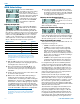
Controls and Functions
LCD Screen
The LCD is a numeric-type Liquid Crystal Display with
several screens that allow settings to be made with the
AUDIO and FREQ buttons, and the UP and DOWN
arrow buttons to configure the transmitter. The trans-
mitter can be turned on in a “standby” mode with the
carrier turned off to make adjustments without the risk
of interfering with other wireless systems nearby.
Power LED
The PWR LED glows green when the batteries are
charged. The color changes to red when there is about
20 minutes of life left. When the LED begins to blink
red, there are only a few minutes of life.
A weak battery will sometimes cause the PWR LED to
glow green immediately after being put into the unit,
but will soon discharge to the point where the LED will
go red or shut off completely.
Audio Input Jack
The XLR input jack on the transmitter accommodates
hand-held, shotgun and measurement microphones.
Phantom power can be set at various levels for use
with a wide variety of electret microphones.
Battery Compartment
The battery compartment door is made of machined
aluminum and is hinged to the housing to prevent it
being damaged or lost.
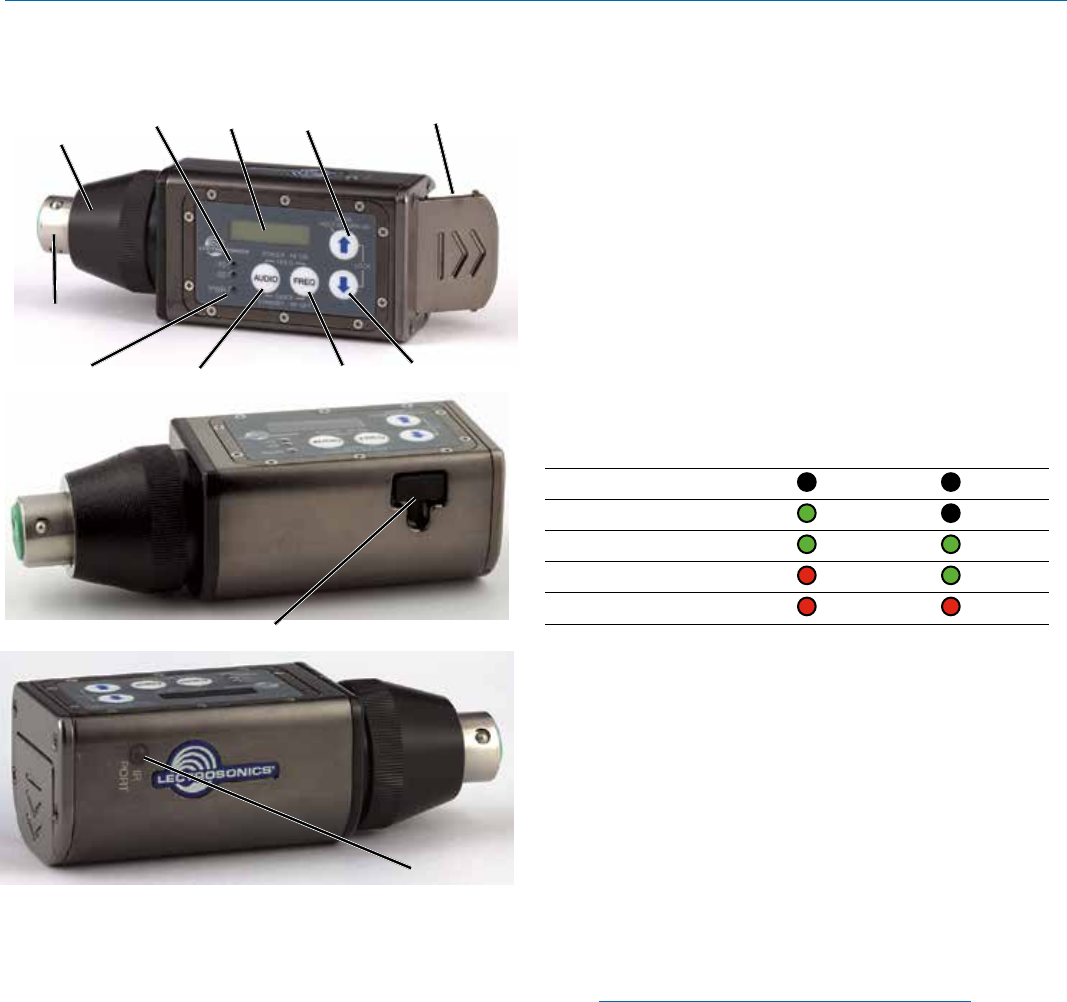
Modulation LEDs
The Modulation LEDs provide a visual indication of the
input audio signal level from the microphone. These
two bicolor LEDs can glow either red or green to indi-
cate modulation levels. Full modulation (0 dB) occurs
when the -20 LED first turns red.
Signal Level -20 LED -10 LED
Less than -20 dB
Off Off
-20 dB to -10 dB Green Off
-10 dB to +0 dB Green Green
+0 dB to +10 dB Red Green
Greater than +10 dB Red Red
Audio Button
The AUDIO button is used to display the audio level
setting, low frequency roll-off and phantom power
mode. Repeatedly pressing the button will cycle
through the available settings, allowing the UP and
DOWN arrow buttons to adjust the values.
Freq Button
The FREQ Button displays the selected operating fre-
quency and also toggles the LCD between displaying
the actual operating frequency in MHz and a two-digit
hexadecimal number. Frequencies can be selected in
either 100kHz or 25kHz steps. The appearance of the
hexadecimal number is different in the 100kHz step
size mode than in the 25kHz step size mode.
NOTE: The FREQ and AUDIO buttons are used
together to enter the standby mode and to turn the
power on or off.
UP/DOWN Arrows and Panel Lockout
The UP and DOWN arrow buttons are used to select
the operating frequency, adjust the audio level, or set
the Compatibility Mode.
Pressing both arrows simultaneously enters the lock
countdown. Holding the two buttons in until the count-
down is completed locks the control panel buttons so
they can only be used to display current settings. “Loc”
is displayed to indicate the controls are locked when a
button is pressed while the panel is locked.
Once locked, the control panel is unlocked by remov-
ing the battery or using the remote control “dweedle”
tones.
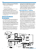
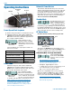
Battery
Compartment
XLR Input Jack
AUDIO Button
LCD
Input
Coupler
FREQ Button
Modulation
LEDs
PWR LED
UP Arrow
DOWN Arrow
USB Port
IR (Infrared) Port