INSTRUCTION MANUAL HMa Wideband Plug-On Transmitter With Digital Hybrid Wireless® Technology Digital Hybrid Wireless® US Patent 7,225,135 Fill in for your records: Serial Number: Purchase Date: Rio Rancho, NM, USA www.lectrosonics.
HMa 2 LECTROSONICS, INC.
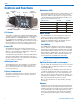
Wideband Digital Hybrid® Plug-On Transmitter Thank you for selecting a Lectrosonics HMa plug-On transmitter.
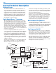
HMa General Technical Description Wideband Design channel as efficiently and robustly as possible, yielding audio performance that rivals that of wholly digital systems, without the power and bandwidth problems inherent in digital transmission. The HMa transmitter uses ±75 kHz wide deviation for an excellent signal to noise ratio and wide dynamic range. The DSP controlled input limiter features a wide range dual envelope design which cleanly limits input signal peaks over 30 dB above full modulation.
Wideband Digital Hybrid® Plug-On Transmitter Input Limiter A DSP-controlled analog audio limiter is employed before the analog-to-digital (A-D) converter. The limiter has a range of more than 30 dB for excellent overload protection. A dual release envelope makes the limiter acoustically transparent while maintaining low distortion. It can be thought of as two limiters in series, a fast attack and release limiter followed by a slow attack and release limiter.
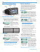
HMa Controls and Functions Input Coupler Modulation LEDs LCD UP Arrow Battery Compartment Modulation LEDs The Modulation LEDs provide a visual indication of the input audio signal level from the microphone. These two bicolor LEDs can glow either red or green to indicate modulation levels. Full modulation (0 dB) occurs when the -20 LED first turns red.
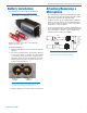
Wideband Digital Hybrid® Plug-On Transmitter Battery Installation The transmitter is powered by two AA batteries. Note: Standard zinc-carbon batteries marked “heavy-duty” or “long-lasting” are not adequate. Attaching/Removing a Microphone The spring loaded coupler under the XLR jack maintains a secure fit to the microphone jack with continuous pressure applied by an internal spring.
HMa Operating Instructions PWR LED Modulation LEDs UP Arrow Automatic Power Restore The firmware will remember the power on/off state and the settings when batteries reach their end of life or are removed. When fresh batteries are installed, the unit will reboot and return to the previous settings without the need to press any buttons. This only works when the unit is fully on and transmitting. It does not work in the Standby Mode.
Wideband Digital Hybrid® Plug-On Transmitter LCD Backlight Settings The LCD backlight can be set to turn off after either 5 minutes or 30 seconds or stay on continuously. Hold the UP arrow in while powering up the unit to enter the setup screen. Press the AUDIO button repeatedly to step through the setup items to reach the backlight settings screen. Use the UP or DOWN arrow button to select the desired setting.
HMa Audio Screen The Audio Screen is used to adjust input gain and low frequency roll-off, and to turn phantom power on and off. Repeatedly pressing the AUDIO button selects the setting. Press and hold the AUDIO button and use the UP and DOWN arrows to adjust the value. Adjusting the Input Gain The control panel Modulation LEDs indicate the modulation level and limiter activity.
Wideband Digital Hybrid® Plug-On Transmitter About the Phantom Power Supply Three phantom voltages are selectable from the control panel. The voltages are: • 5 Volts for lavaliere microphones, • 15 Volts for some professional mics requiring high current and for many common stage mics that will operate over a wide phantom Voltage range of 12 to 48 Volts. With the proper adapter, this position can also be used with T power microphones. See our web site for details on finding or making the proper adapter.
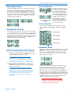
HMa Special Purpose Barrel Adapters P/N 21750 Polarity Reversing Barrel Adapter Earthworks M30 Mic adapter for Earthworks M30 microphone with HM, HMa and UH400a/TM transmitters. This polarity reversing adapter may be needed to correct for asymmetrical current draw in some P48 powered condenser microphones, including older Neumann 100 Series, Rode NTG3 and others. If your microphone does not power on correctly when used with these transmitters, insert the adapter between the transmitter and microphone.
Wideband Digital Hybrid® Plug-On Transmitter Accessories PHTRAN3 Replacement leather pouch with clear plastic screen cover, rotating belt clip and snap closure. Included with transmitter at purchase. MCA-TPOWER This cable adapter is to be used with the UH200D, UH400, HM and HMa plug-on transmitters with T-powered microphones. It will protect a T-power mic against the 48V phantom power setting in the transmitter while allowing normal operation.
HMa Troubleshooting Before going through the following chart, be sure that you have good batteries in the transmitter. It is important that you follow these steps in the sequence listed. SYMPTOM POSSIBLE CAUSE TRANSMITTER PWR LED OFF 1) 2) AUDIO LEVEL LEDs NOT LIGHTING 1) 2) 3) 4) Batteries are inserted backwards or dead. Transmitter not powered up. (See Operating Instructions, Power UP and Boot Sequence.) Gain control set to minimum. Batteries are inserted backwards or dead. Check PWR LED.
Wideband Digital Hybrid® Plug-On Transmitter SYMPTOM POSSIBLE CAUSE HISS AND NOISE -- AUDIBLE DROPOUTS 1) 2) 3) 4) Transmitter gain (audio level) far too low. Receiver antenna missing or obstructed. Operating range too great. Signal interference. Turn off transmitter. If receiver’s signal strength indicator does not drop to nearly zero, this indicates an interfering signal may be the problem. Use a clear operating frequency.
HMa Specifications and Features Operating frequencies: (Frequency usage varies by country) Band A1: 470.100 - 537.575 Band B1: 537.600 - 614.375 Band C1: 614.400 - 691.175 Band D1: 691.200 - 767.
Wideband Digital Hybrid® Plug-On Transmitter FCC Notice: For body worn operation, this transmitter model has been tested and meets the FCC RF exposure guidelines when used with the Lectrosonics accessories supplied or designated for this product. Use of other accessories may not ensure compliance with FCC RF exposure guidelines. Contact Lectrosonics if you have any questions or need more information about RF exposure using this product.
Service and Repair If your system malfunctions, you should attempt to correct or isolate the trouble before concluding that the equipment needs repair. Make sure you have followed the setup procedure and operating instructions. Check the interconnecting cables and then go through the Troubleshooting section in this manual. We strongly recommend that you do not try to repair the equipment yourself and do not have the local repair shop attempt anything other than the simplest repair.
LIMITED ONE YEAR WARRANTY The equipment is warranted for one year from date of purchase against defects in materials or workmanship provided it was purchased from an authorized dealer. This warranty does not cover equipment which has been abused or damaged by careless handling or shipping. This warranty does not apply to used or demonstrator equipment. Should any defect develop, Lectrosonics, Inc. will, at our option, repair or replace any defective parts without charge for either parts or labor.