
User's Manual

IFBR1a, IFBR1a/E01, IFBR1a/E02
LECTROSONICS, INC.
4
Features and Functions
The frequency agile IFB R1a FM Receiver is designed
to operate with the Lectrosonics IFB transmitters and
compatible Digital Hybrid transmitters. Microprocessor
control of frequencies within each frequency block pro-
vides the ability to work around interference problems
quickly and simply.
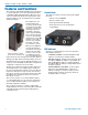
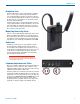
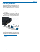
The R1a includes a leather
pouch with a rotating belt clip
The unique microcon-
troller design in this
receiver provides simple
one knob and one LED
operation for audio level,
switching frequencies
(channels), and easy
on-the-fly programming.
The receiver frequency
can be set by manually
using the two rotary HEX
switches on the side of
the unit or by using the
automatic scan and
store function, or both.
When powered ON, the
receiver will default to
the frequency set by the
switches. A nonvolatile
memory can store up to
ten additional frequen-
cies accessible by press-
ing the knob. The stored frequencies remain in memory
during power OFF and even with the battery removed.
The IFB R1a Receiver uses 20 kHz FM deviation for ef-
ficient use of the bandwidth and includes a single band
compandor to suppress noise in the audio.
The Pilot Tone squelch prevents the audio output from
opening when there is no signal being received from
the associated transmitter. The pilot tones are different
frequencies than those used in Lectrosonics wireless
microphone systems to prevent the signal from an IFB
transmitter from opening the squelch on a wireless
microphone receiver.
The receiver operates on one 9 Volt alkaline. lithium
or rechargeable battery for up to 8 hours and features
a tricolor LED low battery indicator. The voltages are
internally regulated for stability.
The receiver is housed in a compact, rugged, light-
weight aluminum enclosure. The unit features a durable
removable belt clip and an integral rotating battery
compartment door.
Control Knob
The single front panel control knob performs multiple
functions;
• Rotate for Power ON/OFF
• Rotate for Audio Level
• Push quick, Channel Switching
• Push and rotate for Scan and Channel
programming
LED Indicator
The three color LED indicator on the front panel pro-
vides multiple functions:
CHANNEL NUMBER: The LED will blink a rapid
sequence to indicate the channel number
BATTERY STATUS: During normal operation, when
the LED is GREEN, the battery is good. When the
LED is YELLOW the battery is getting low. When
the LED is RED, the battery is nearly depleted and
should be replaced.
PROGRAMMING FUNCTIONS: In the program-
ming mode, the LED will blink at a fast rate to
indicate scanning for an active frequency. It also
flashes briefly to indicate a frequency has been
programmed into a channel.