
User's Manual


T4
LECTROSONICS, INC.
4
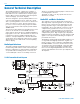
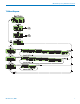
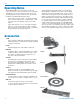
The T4 IFB Transmitter is comprised of a number of
functional subsystems, including Audio Input Interface,
DSP Audio Processor and Pilot Tone, Frequency Syn-
thesizer, Microcontroller, Transmitter, Antenna System
and Power Supply. (See block diagram.)
The T4 is designed to operate primarily with the Lectro-
sonics R1 and R1A IFB receivers, and is also capab-
able of operating with the Lectrosonics 100 Series, 200
Series, 400 Series receivers. The T4 features micro-
processor control of 256 operating frequencies within
any one of at least nine UHF frequency bands and the
944MHz band.
The T4 uses 20 kHz deviation in the IFB and 100 series
modes for an effi cient use of bandwidth. The 200
Series and 400 Series modes use 75kHz bandwidth for
high signal to noise ratio. The transmitter circuits are all
regulated for frequency stability and high audio per-
formance. The input amplifi er is a discreet differential
circuit which can be adjusted to allow the use of many
different input sources with robust overload capability
without clipping.
Audio Input Interface
The input sensitivity and XLR pin functions can be cus-
tomized using a DIP switch located on the back panel.
Different combinations of gain and input confi gurations
are possible without rewiring the mic connector. Pin
1 of the XLR input connector is normally connected
directly to ground but an internal jumper can be moved
if a fl oating input is desired.
The Audio (+) and (–) are “dry” inputs and can each
withstand +/- 50 VDC.
Audio DSP and Noise Reduction
The original Lectrosonics IFB system was designed
with single band compand ing which is an audio device
that processes (compresses) the input signal so that
the large dynamic ranges of the input signals can be
transmitted to the receiver without overload or noise. A
complementary system in the receiver recovers (de-
compresses) the original dynamics of the signal for full
audio quality. Compression and expansion ratios are
complementary at 2:1. High frequency pre-emphasis is
implemented in the transmitter to provide another 10 dB
signal to noise improvement. Matching de-emphasis is
provided in all receivers.
The IFBT4 is designed with Audio Digital Signal Proces-
sor algorithms that digitally emulate the original com-
pandor circuits in order to maintain compatability with
the IFBR1/IFBR1a, 100 Series, and 200 Series receiv-
ers using the same analog FM links. This same DSP
circuitry also provides an algorithm compatible with
the Lectosonics Digital Hybrid Wireless™ 400 Series
systems and eliminates the need for pre-emphasis and
de-emphasis.
General Technical Description
T4 IFB Transmitter Block Diagram