
User's Manual


Multi-Frequency IFB Transmitter
Rio Rancho, NM
5
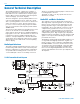
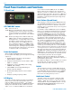
Pilot Tone
The T4/R1A system uses an ultrasonic tone modula-
tion of the carrier to operate the receiver squelch. This
“pilot tone” consists of a 29.997 kHz signal in the DSP
and is mixed with the audio signal to the FM modulator.
The pilot tone controls the audio output muting of the
receiver and is fi ltered out of the audio signal immedi-
ately after the detector in the receiver so that it does not
infl uence the compandor or various gain stages.
The benefi t of the pilot tone squelch system is that the
receiver will remain muted until it receives the pilot tone
from the matching transmitter, even if a strong RF sig-
nal is present on the carrier frequency of the system.
The T4 DSP also generates pilot tones to operate with
the 200 Series and 400 Series receivers as well as
several other popular system receivers.
Frequency Synthesizer
The transmitter uses a synthesized, frequency select-
able main oscillator. The frequency is extremely stable
over a wide temperature range and over time. The
push-button switches, located on the front panel of the
unit, provides the user access to set 256 frequencies in
100 kHz steps over a 25.5 MHz range. This signifi cantly
alleviates carrier interference problems in mobile or
traveling applications.
Power Delay
There is a fi ve second power-ON/OFF delay to prevent
audio thumps when switching from XMIT to TUNE or
from TUNE to OFF. This delay also gives the Frequency
Synthesizer time to fully stabilize. When the transmitter
is powered OFF, the Pilot Tone is fi rst turned off muting
the audio at the receiver before the rest of the transmit-
ter is powered down. This prevents clicks, thumps or
feedback from entering the sound system.
Microcontroller
Frequency adjustment and display are handled by
the microprocessor. Nonvolatile memory is provided
for holding the last frequency used, even if power is
removed from the unit for any length of time. Each time
the transmitter is powered up, it will display the last
frequency used.
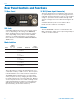
Transmitter
The T4 transmitter operates at 250 mW, more power-
ful than most IFB systems on the market today. The
higher power ensures a clean signal free of dropouts
and noise. The transmitter circuits are buffered and
fi ltered for exceptional spectral purity. The extra clean
signal that results reduces the chances for interference
between multiple transmitter installations.
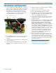
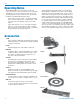
Antenna System
The antenna on the T4 consists of a fl exible 1/4 wave-
length bronze cable, detachable via a BNC connector.
The 50 ohm output connector works conveniently with a
variety of remote antennas for installation in studios and
production trucks & vans.