
User's Manual


T4
LECTROSONICS, INC.
8
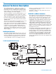
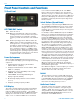
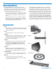
T4 Rear Panel
XLR Jack
A standard XLR female jack accepts a variety of input
sources depending on the setting of the MODE dip
switch. XLR pin functions can be changed to suit the
source depending on the positions of the individual
switches. For detailed information on the setting of
these switches see the INSTALLATION AND OPERA-
TION section.
Mode Switches
Switch
Positions Input
Name 1 2 3 4 XLR Pins Balanced Sensitivity
CC TTTS 3 = Audio No -10 dBu
1 = Common
MIC SSST 2 = Hi Yes -42 dBu
3 = Lo
1 = Common
LINE SSTT 2 = Hi Yes 0 dBu
3 = Lo
1 = Common
RTS1 STTT 2 = Hi No 0 dBu
1 = Common
RTS2 TTTT 3 = Hi No 0 dBu
1 = Common
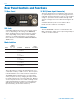
Rear Panel Controls and Functions
These dip switches confi gure the XLR input jack to ac-
commodate a variety of audio sources. The rear panel
is marked with the most common switch combinations.
The MODE switches allow the T4 to accommodate a
variety of input sources by changing the input sensitiv-
ity and the pin functions of the input XLR jack. Marked
on the rear panel are the most common settings. Each
setting is detailed below. Switches 1 and 2 adjust the
XLR pin functions while switches 3 and 4 adjust the
input sensitivity. (mode switch chart here)
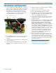
12 VDC (Power Input Connector)
The T4 is designed to be used with the CH20 external
(or equivalent) power source, which is plugged into the
6-18 VDC external power input connector. The nominal
voltage to operate the unit is 12 VDC; although it will
operate at voltages as low as 6 VDC and as high as 18
VDC.
A suitable alternate power source must be able to
handle 200 mA continuous consumption.
Antenna
The T4’s ANTENNA connector is a standard 50 ohm
BNC confi guration, which can accept an integral whip or
a cable to a remote antenna.