
User's Manual


Multi-Frequency IFB Transmitter
Rio Rancho, NM
9
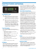
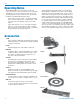
1) The T4 transmitter is shipped with pin 1 of the XLR
input connector tied directly to ground. If a fl oating
input is desired, a Ground Lift Jumper is provided.
This jumper is located inside the unit on the PC
board near the rear panel XLR jack. If a fl oating
connection is desired, open the unit and move the
Ground Lift Jumper to the desired location.
Location of Ground Lift Jumper:
Installation and Operation
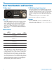
2) Set the MODE switches on the rear panel to match
the specifi c input source to be used. (See Mode
Switches.)
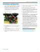
3) Insert the power supply plug into the 6-18 VDC jack
on the rear panel.
4) Insert the microphone XLR plug into the input jack.
Ensure the pins are aligned and that the connector
locks in.
5) Attach the antenna (or antenna cable) to the BNC
connector on the rear panel.
6) Mute the sound source connected to the T4.
7) Set the OFF/TUNE/XMIT switch to TUNE.
8) Step MENU to the frequency/channel window and
adjust the transmitter to the desired frequency with
the front panel FREQ up/down buttons.
9) Position the microphone. The microphone should
be placed in the position in which it will be used
during the program.
10) Step the MENU button to the LEVEL window. While
speaking at the same voice level that will be used
during the program, observe the display audio
meter. Using the DOWN button, set the AUDIO
LEVEL gain to a low level, -10 or -18 so that the au-
dio peaks are well below 0dB limiting on the scale.
Then gradually adjust the AUDIO LEVEL gain with
the UP button until the audio meter occasionally
peaks at the maximum of 0dB on the scale“. -There
is over 15 dB of limiting range without overload
above the “0” indication. It is desirable that the
audio peaks at or slightly above 0dB about 5-10
percent of the time during use.
11) Once the transmitter audio gain has been set, the
receiver and other components of the system can
be energized and their audio levels adjusted. Set
the power switch on the T4 transmitter to the XMIT
and adjust the associated receiver and sound sys-
tem level as required.
Note: There will be a delay between the moment
the transmitter is energized and when audio
will actually appear at the receiver output. This
intentional delay eliminates turn on thumps, and is
controlled by the pilot tone squelch control.