
User's Manual


LR
LECTROSONICS, INC.
6
IR PORT
AUDIO
OUT
This device complies with part 15 of the FCC rules.
Operation is subject to the condition that this device
does not cause harmful interference.
CAN RSS-Gen/CNR-Gen
CAN ICES-3 (B)/NMB-3(B)
Model: LR-XX Made in the USA
Serial No. XXXXX
Frequency block XXX (XXX.X - XXX.X MHz)
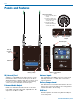
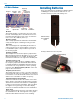
Panels and Features
IR (infrared) Port
Settings for compatibility mode and frequency can be
transferred from the receiver via this port to an IR en-
abled transmitter to simplify setup. The receiver is used
to scan for a clear frequency, and the new frequency
can be sent to the transmitter via the IR ports.
Balanced Audio Output
Balanced or unbalanced audio from mic to line level
is provided on the TA3 output jack; adjustable in 1 dB
steps from -50 dBu to +5 dBu.
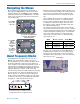
Antenna Inputs
Two standard 50 ohm SMA connectors can be used
with whip antennas or coaxial cable connected to
remote antennas.
Battery Compartment
Two AA batteries are installed as marked on the rear
panel of the receiver. The battery door is hinged and
remains attached to the housing.
USB Port
Firmware updates are made easy with the USB port
on the side panel.
Balanced Audio
Output
IR (infrared)
Port
Antenna Inputs
Belt clip
mounting
hole
USB Port
Battery Compartment
Door
Battery polarity
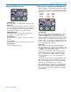
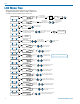
1
2
3
Three-Pin TA3 Male
1) Chassis ground (cable
shield)
2) Positive polarity term-
ianl for balanced audio
circuits (aka “hot”)
3) Negative polarity
terminal for balanced
circuits (aka “cold”)