
User's Manual


LT
LECTROSONICS, INC.
20
Microphone RF Bypassing
When used on a wireless transmitter, the microphone
element is in the proximity of the RF coming from the
transmitter. The nature of electret microphones makes
them sensitive to RF, which can cause problems with
microphone/transmitter compatibility. If the electret
microphone is not designed properly for use with wire-
less transmitters, it may be necessary to install a chip
capacitor in the mic capsule or connector to block the
RF from entering the electret capsule.
Some mics require RF protection to keep the radio sig-
nal from affecting the capsule, even though the trans-
mitter input circuitry is already RF bypassed.
If the mic is wired as directed, and you are having dif-
ficulty with squealing, high noise, or poor frequency
response, RF is likely to be the cause.
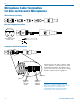
The best RF protection is accomplished by installing RF
bypass capacitors at the mic capsule. If this is not pos-
sible, or if you are still having problems, capacitors can
be installed on the mic pins inside the TA5F connec-
tor housing. Refer to the diagram below for the correct
locations of capacitors.
Use 330 pF capacitors. Capacitors are available from
Lectrosonics. Please specify the part number for the
desired lead style.
Leaded capacitors: P/N 15117
Leadless capacitors: P/N SCC330P
All Lectrosonics lavaliere mics are already bypassed
and do not need any additional capacitors installed for
proper operation.
CAPSULE
CAPSULE
SHIELD
AUDIO
SHIELD
AUDIO
BIAS
TA5F
CONNECTOR
TA5F
CONNECT
OR
2-WIRE MIC 3-WIRE MIC
Capacitors next
to mic capsule
Capacitors in
TA5F connector
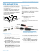
Line Level Signals
The wiring for line level and instrument signals is:
• Signal Hot to pin 5
• Signal Gnd to pin 1
• Pin 4 jumped to pin 1
This allows signal levels up to 3V RMS to be applied
without limiting.
NOTE for line level inputs only (not instrument):
If more headroom is needed, insert a 20 k resistor
in series with pin 5. Put this resistor inside the
TA5F connector to minimize noise pickup. The
resistor will have little or no effect on the signal if
the input is set for instrument.
See Fig. 8 on
previous page
Line Level
Normal Wiring
Line Level
More Headroom
(20 dB)