R170 RECEIVER OPERATING INSTRUCTIONS and trouble-shooting guide LECTROSONICS, INC.
INTRODUCTION Thank you for selecting the Lectrosonics R170 receiver. This system provides reliable performance and flexibility for a wide range of uses. The high selectivity provides protection from interference while the high sensitivity increases the operating range and resistance to dropouts. A unique automatic squelching system eliminates excess noise output from the receiver when the transmitter is turned off.
GENERAL DESCRIPTION The R170 receiver utilizes a two stage quartz crystal oscillator to assure that the frequency will not drift. Custom made high Q toroidal filters in the RF and IF stages reject interfering adjacent signals and provide over 100 dB of image rejection. Dual gate MOS FET semi-conductors in the RF amplifier and mixer provide excellent sensitivity and resistance to RF overload.
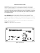
RECEIVER FRONT PANEL MODULATION - Indicates the modulation (audio level) of the incoming signal. The green LED indicates an adequate modulation level. The red LED indicates maximum or "peak" modulation. OUTPUT - VOLUME ATTENUATOR - An output attenuator is used to adjust the output level of the two balanced outputs (XLR and 1/4") on the rear panel of the receiver. When the knob is in a fully clock wise position, the output at the jack will be 100mV when the signal is at full modulation.
RECEIVER REAR PANEL ANTENNA terminal -- A standard PL 259 connector for mounting the A-185PL antenna, or connecting the A-185Coax remote antenna. 12V DC INPUT -- Connect the power supply here -- the CH-12 AC adapter is supplied with the receiver for powering the unit from a 110V AC outlet -- the receiver may also be powered from 12 Volt DC sources using the correct plug; the center pin is positive(+). (Switchcraft S-760 power plug) AUDIO OUTPUTS BAL MIC LEVEL -- 3 pin XLR at microphone level (100mV max.
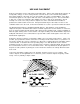
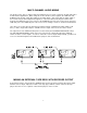
USE AND PLACEMENT A wireless transmitter sends a radio signal out in all directions. Indoors, this signal will often bounce off nearby walls, ceilings, etc. and a strong reflection can arrive at the receiver antenna along with the direct signal. Outdoors, reflections can occur from nearby cars, trucks or metal buildings. If the direct and reflected signals are out of phase with each other, a cancellation may occur. The result would be a "drop out.
OPERATING INSTRUCTIONS SET UP AND OPERATION SEQUENCE 1) CONNECT POWER CORD -- Plug the connector into the jack labeled "12 VDC ". Insert the plug fully into the jack. 2) ATTACH AND EXTEND THE ANTENNA FULLY 3) CONNECT THE AUDIO CABLE/S A. For playback from a tape player, plug into "AUDIO IN" B. The sound system plugs into "BAL MIC" C. An alternate plug for the sound system is "HI Z BAL" D. To record, plug a tape recorder into "LINE OUT".
MULTI-CHANNEL AUDIO MIXING The R170 receiver offers a unique feature that eliminates the necessity of using an external audio mixer in multi-channel applications. When using two or three R170 receivers together, the LINE OUT and AUDIO IN jacks provide "unity gain" mixing of the audio signals. This means that the audio output of the receivers may be mixed together through these connectors without affecting the volume levels.
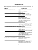
TROUBLESHOOTING Before going through the following chart, be sure that you have a good battery in the transmitter. It is important that you follow these steps in the sequence listed. SYMPTOM POSSIBLE CAUSE TRANSMITTER BATTERY LED OFF 1) External LED is turned off. Check internal slide switch. 2) Battery is inserted backwards. 3) Battery is dead. NO TRANSMITTER MOD LEVEL LEDs 1) Gain control turned all the way down. 2) Battery is in backwards. Check power LED.
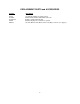
REPLACEMENT PARTS and ACCESSORIES Part No.
SERVICE AND REPAIR If your system malfunctions, you should attempt to correct or isolate the trouble before concluding that the equipment needs repair. Make sure you have followed the setup procedure and operating instructions. Check out the inter-connecting cords and then go through the TROUBLE SHOOTING section in the manual We strongly recommend that you do not try to repair the equipment yourself and do not have the local repair shop attempt anything other than the simplest repair.
SPECIFICATIONS AND FEATURES R170 RECEIVER Operating frequencies: 150 to 216 MHz crystal controlled Sensitivity: 1.0uV for 20dB SINAD 2.0uV for 50dB S/N ratio Signal/noise ratio: 96 dB flat; 100 dB A-weighted Squelch quieting: greater than 100 dB AM rejection: -40 dB (10uV to 0.1 Volts) Modulation acceptance: ±15kHz Image/spurious rejection: greater than 100 dB Audio outputs: * XLR: 200 Ohm balanced; 100mV max. * ¼ inch: 600 Ohm; 700 mV max. (500 mV max.
LIMITED ONE YEAR WARRANTY The equipment is warranted for one year from date of purchase against defects in materials or workmanship provided it was purchased from an authorized dealer. This warranty does not cover equipment which has been abused or damaged by careless handling or shipping. This warranty does not apply to used or demonstrator equipment. Should any defect develop, we will, at our option, repair or replace any defective parts without charge for either parts or labor.