R185 VHF RECEIVER OPERATING INSTRUCTIONS and trouble-shooting guide LECTROSONICS, INC.
INTRODUCTION Thank you for selecting the Lectrosonics system. The R185 represents over 80 combined years of experience in the design of RF and audio devices, and sets new standards for RF performance and flexibility. The R185 receiver was designed for professional users who demand outstanding performance and flexibility. It is a single antenna, single channel design compatible with all Lectrosonics VHF 185 Series transmitters.
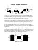
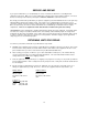
GENERAL TECHNICAL DESCRIPTION The R185 receiver is comprised of five functional subsystems: the RF front-end, the double balanced mixer/local oscillator, the first IF filter, the second IF filter and demodulator, the compandor and audio output section. 6 SECTION HELICAL RESONATOR ANT ACTIVE FILTERS SEPARATE NOISE AND AUDIO DBL BAL DIODE MIXER DBL BAL ACTIVE MIXER SQUELCH IF AMP 0.
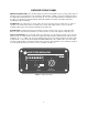
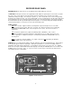
RECEIVER FRONT PANEL MODULATION INDICATORS Nine (9) LEDs indicate the audio level (modulation) of the incoming signal, which are typically used for proper adjustment of the transmitter’s "MIC LEVEL" or "GAIN." The left-most LED (red) functions as a pilot lamp to indicate that the receiver is powered up. The seven green LEDs indicate the modulation level of the signal. The right-most yellow LED indicates maximum modulation and that the transmitter audio input is probably being driven into limiting.
RECEIVER REAR PANEL ANTENNA INPUT This input connects to any 50 Ohm antenna with a BNC type connector. 12 VDC INPUT This input connects to the supplied CH-12 AC adapter for powering the receiver from a 110/120V AC source. The receiver may also be powered from external 12 Volt DC sources using the correct plug (Switchcraft S-760 power plug). The center pin is positive. (+). If the external DC source is of the wrong polarity, the R185 receiver will not operate.
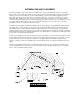
ANTENNA USE AND PLACEMENT A wireless transmitter sends a radio signal out in all directions. Indoors, this signal will often bounce off nearby walls, ceilings, etc. and a strong reflection can arrive at the receiver antenna along with the direct signal. Outdoors, reflections can occur from nearby cars, trucks or metal buildings. If the direct and reflected signals are out of phase with each other at the receiver antenna, a cancellation will occur. The result is a "drop-out.
OPERATING INSTRUCTIONS 1) Connect the power supply. 2) Attach the antenna. 3) Connect the audio cable from the sound system or recorder to the receiver. 4) Set the front panel switch to the "MUTE" position. Check to see that the red POWER LED lights up (the leftmost LED in the 9-LED display). 5) Adjust the transmitter "gain." THIS IS PERHAPS THE MOST IMPORTANT STEP IN THE SET UP PROCEDURE. See your transmitter manual for specific directions on the proper gain adjustment of your particular transmitter.
TROUBLESHOOTING Before going through the following chart, be sure that you have a good battery in the transmitter. It is important that you follow these steps in the sequence listed. SYMPTOM POSSIBLE CAUSE RECEIVER RF LAMP OFF 1) 2) 3) 4) Transmitter not turned on. Transmitter battery is dead. Receiver antenna missing or improperly positioned. Transmitter and receiver not on same frequency. Check labels on transmitter and receiver. 5) Operating range is too great.
SERVICE AND REPAIR If your system malfunctions, you should attempt to correct or isolate the trouble before concluding that the equipment needs repair. Make sure you have followed the setup procedure and operating instructions. Check out the inter-connecting cords and then go through the TROUBLE SHOOTING section in the manual We strongly recommend that you do not try to repair the equipment yourself and do not have the local repair shop attempt anything other than the simplest repair.
R185 SPECIFICATIONS AND FEATURES Operating frequencies: 150 to 216 MHz, crystal controlled Sensitivity: 1.7uV for 50dB S/N ratio with compandor Better than 0.5uV for 20 dB quieting without compandor; Signal/noise ratio: 96 dB (A-weighted), typical overall system Squelch quieting: Greater than 110 dB AM rejection: -60 dB (10uV to 0.1 Volts) Modulation acceptance: ± 15 kHz Image and spurious rejection: Greater than 100 dB Third order intercept: +5 dBm Audio outputs: * XLR: 200 Ohm bal.
LIMITED ONE YEAR WARRANTY The equipment is warranted for one year from date of purchase against defects in materials or workmanship provided it was purchased from an authorized dealer. This warranty does not cover equipment which has been abused or damaged by careless handling or shipping. This warranty does not apply to used or demonstrator equipment. Should any defect develop, we will, at our option, repair or replace any defective parts without charge for either parts or labor.