
User's Manual


UHF Wireless Diversity Receiver
Rio Rancho, NM
7
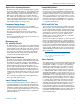
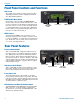
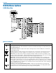
1. Connect the power cord from the power supply to
the Power Input Jack.
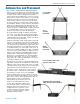
2. Attach the antennas or antenna cables to the MAIN
ANT and DIV ANT BNC connectors.
3. Press the POWER/PREV MENU button to turn on
the unit on. Check to see that the LCD displays the
three-screen Power Up Sequence:
Lectrosonics
R400A VXX where VXX is the current firmware
version installed
Block XX where XX is the frequency tuning range
block number
After the Power Up Sequence is displayed, the
Main Window appears and the R400A is ready for
operation.
4. Ensure the receiver and transmitter are set to
the same Compatibility Mode, then locate a clear
operating frequency (see Frequency Coordination.)
Then set the Transmitter Frequency Select Switch-
es to match the receiver’s operating frequency.
(See R400A Menu Options.)
5. Turn the transmitter on and verify that an RF signal
is indicated on the LCD.
6. Connect an audio cable to the appropriate audio
output jack. Because the audio outputs operate in-
dependently, external equipment can be connected
to either, or both output jacks.
7. Locate a clear operating frequency. The easiest
method is to use SmartTune™ and then set the
transmitter frequency indicated on the display.
Note: For more detailed instructions, see “Using
SmartTune™ and the Scan Function” on page 16.
8. Refer to the associated transmitter operating in-
structions and adjust the transmitter gain.
Warning: This is perhaps the most important
step in the setup procedure.
In general, adjust the transmitter gain so that the
voice peaks will cause the audio modulation level
indicators on both the receiver and transmitter to
show full modulation on the loudest peak audio
levels. Normal levels should cause the R400A’s
audio level bar to fluctuate fully resulting in the best
possible signal to noise ratio for the system.
Note: A common mistake is to use the transmitter
audio gain control to set the overall audio level
of the entire system. The transmitter gain
control is not a volume control and must be set
independently of the overall system audio level.
The transmitter gain control is only used to set the
proper modulation of the transmitter. It is used to
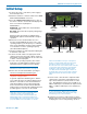
Initial Setup
POWER/
PREV MENU
Button
MENU ControlLCD Screen
Main
Antenna Input
Diversity
Antenna Input
Balanced
Audio OutputPower Input Jack
Unbalanced
Audio Output
match the transmitter to the type of microphone
and the sound levels that will be present at that
microphone. We encourage users to either
disconnect the rest of the sound system or turn the
sound system gain to minimum to prevent either
feedback or overload as the transmitter gain is
set. Only after the transmitter gain control is set
should the gain of the rest of the audio system be
adjusted to achieve the desired sound or signal
levels.
9. Use the Level or Tone menus to adjust the audio
output levels to match the required input level of
any connected devices (camera, mixer, recorder,
etc.). The adjustment range is from -50 dBu to +5
dBu in 1 dBu steps for the balanced output and -55
dBu to +0 dBu in 1 dBu steps for the unbalanced
output.
Note: The test tone output is especially useful for
an exact level match. With the test tone running,
adjust for the maximum desired peak level using
the metering on the connected device.
10. If desired, access the LockSet menu to lock the
R400A front panel controls to prevent inadvertently
modifying the receiver settings during operation.