
User's Manual
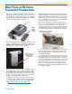

Super-Minature Belt Pack Transmitter
Rio Rancho, NM
11
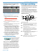
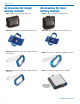
The wiring diagrams included in this section represent
the basic wiring necessary for the most common types
of microphones and other audio inputs. Some micro-
phones may require extra jumpers or a slight variation
on the diagrams shown.
It is virtually impossible to keep completely up to date
on changes that other manufacturers make to their
products, thus you may encounter a microphone that
differs from these instructions. If this occurs please call
our toll-free number listed under Service and Repair in
this manual or visit our web site at:
www.lectrosonics.com
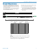
SM Equivalent Input Circuit Wiring
10k
1k
5
4
3
2
1
To Virt
ual Ground
Audio Amplifier
BIAS
MIC
BIAS SELECT
LINE IN
GND
+
30uF
+5 VDC
Servo Bias
Pin 4 to Pin 1 = 0 V
Pin 4 Open = 2 V
Pin 4 to Pin 2 = 4 V
+
To Limiter Control
30uF
500 Ohm
100 Ohm
2.7K
200 Ohm
+
3.3uF
100 Ohm
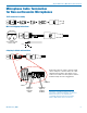
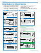
Audio input jack wiring:
5-Pin Input Jack Wiring
PIN 1 Shield (ground) for positive biased electret lava-
liere microphones. Shield (ground) for dynamic
microphones and line level inputs.
PIN 2 Bias voltage source for positive biased electret
lavaliere microphones.
PIN 3 Low impedance microphone level input for
dynamic microphones. Also accepts hand-held
electret microphones provided the microphone
has its own built-in battery.
PIN 4 Bias voltage selector for Pin 3. Pin 3 voltage (0, 2
or 4 volts) depends on Pin 4 connection.
Pin 4 tied to Pin 1: 0 V
Pin 4 Open: 2 V
Pin 4 to Pin 2: 4 V
PIN 5 High impedance, line level input for tape decks,
mixer outputs, musical instruments, etc.
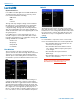
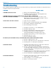
It is actually a good idea to turn the gain up to maxi-
mum and listen for distortion or compression to get a
feel for how much headroom is available.
Signal Level -20 LED -10 LED
Less than -20 dB Off Off
-20 dB to -10 dB
Green Off
-10 dB to +0 dB Green Green
+0 dB to +10 dB
Red Green
Greater than +10 db Red Red
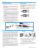
Note: Different voices will usually require different gain set-
tings, so check this adjustment as each new person uses the
system. If several different people will be using the transmitter
and there is not time to make the adjustment for each indi-
vidual, adjust it for the loudest voice.
1) With the transmitter powered off, plug in the mi-
crophone and make sure the connector is firmly
seated.
Warning: If the systems is powered up while
connected to a live sound system, be careful
to turn the sound system level down first or
severe feedback can occur.
2) Place the transmitter in Standby Mode or turn it on
for normal use.
3) Position the microphone in the location where it will
be used in actual operation.
4) Observe the Modulation LEDs while speaking or
singing into the microphone at the same voice level
that will be used during operation. While holding
the AUDIO button, press the UP or DOWN arrow
buttons until the both the -20 and -10 LEDs glow
green, with the -20 LED occasionally flickering red.
This will maximize the signal to noise ratio of the
system with full modulation and provide subtle limit-
ing to prevent overload and audible compression.
5) If the unit was set up in Standby Mode, it will be
necessary to turn the transmitter off, then power it
up again in normal operation so the RF output will
be on. Then the other components in the sound or
recording system can be adjusted.
Locking or Unlocking the Controls
Control Panel Locked
The Lock mode protects the
transmitter from accidental
changes to its settings.
Simultaneously press both
the Up and Down arrow
buttons to start the countdown timer. When the timer
reaches zero, “Loc” is displayed and the controls are
locked. Settings can be reviewed but not changed.
Once the transmitter is locked, it cannot be unlocked or
powered off using the buttons. The only ways to unlock a
locked transmitter are to remove the battery or unlock it
using the remote control. The remote control will work only
if the transmitter was previously configured to respond
to the remote control. The unit will always power up in
“unlocked” mode.