
User's Manual

SMV Series
LECTROSONICS, INC.
12
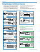
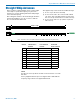
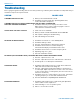
3 WIRE MIC2 WIRE MIC
CAPSULE
CAPSULE
SHIELD
AUDIO
SHIELD
AUDIO
BIAS
Alternate locations for bypass capacitors
TA5F
CONNECTOR
TA 5F
CONNECTOR
Preferred locations for bypass capacitors
Install the capacitors as follows: Use 330 pF capaci-
tors. Capacitors are available from Lectrosonics. Please
specify the part number for the desired lead style.
Leaded capacitors: P/N 15117
Leadless capacitors: P/N SCC330P
All Lectrosonics lavaliere mics are already bypassed
and do not need any additional capacitors installed for
proper operation.
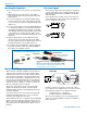
Installing the Connector:
1) If necessary, remove old connector from microphone
cable.
2) Slide Rubber Boot onto microphone cable with the
large end facing away from the microphone. (See illus-
tration above.)
3) If necessary, slide the 1/8-inch black shrink tubing
onto the mircrophone cable. (This tubing is needed
for some cables to ensure the cable fits snugly in the
rubber boot.)
4) Use the resistors and connector included with this kit
to configure the TA5F to your particular microphone.
(See Wiring Diagrams below.) A length of .065 OD
clear tubing is included if insulating the resistor leads
or shield wire is necessary. (Remove rubber strain
relief from connector backshell by pulling it out of the
backshell.)
5) Slide the Strain Relief over the TA5F Insert and
crimp as shown to the right. Then insert the TA5F
Insert and Strain Relief in the TA5F Latchlock. Screw
the TA5F Flex Relief onto the TA5F Latchlock.
6) If needed, position and shrink the 1/8-inch shrink tub-
ing on the microphone cable, then slide the Rubber
Boot down over the TA5F connector.
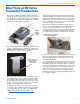
Microphone RF Bypassing
When used on a wireless transmitter, the microphone
element is in the proximity of the RF coming from the
transmitter. The nature of electret microphones makes
them sensitive to RF, which can cause problems with
the microphone/transmitter compatibility. If the electret
microphone is not designed properly for use with wire-
less transmitters, it may be necessary to install a chip
capacitor in the mic capsule or connector to block the
RF from entering the electret capsule.
Some mics require RF protection to keep the radio
signal from affecting the capsule, even though the
transmitter input circuitry is already RF bypassed (see
schematic diagram).
If the mic is wired as directed, and you are having dif-
ficulty with squealing, high noise, or poor frequency
response, RF is likely to be the cause.
The best RF protection is accomplished by installing RF
bypass capacitors at the mic capsule. If this is not pos-
sible, or if you are still having problems, capacitors can
be installed on the mic pins inside the TA5F connector
housing.
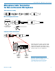
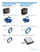
TA5F Latchlock
Insert
Insulator
Strain Relief
TA5F Backshell
with Strain Relief
Remove strain relief if
using dust boot
TA5F Backshell
(Strain Relief removed)
Dust Boot (P/N 35510)
Note: If you use the dust boot, remove the rubber
strain relief that is attached to the TA5F cap, or the
boot will not fit over the assembly.
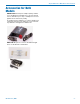
SMKITTA5 Connector kit for SMV series
transmitters, 5-pin TA5F plug with sleeve
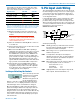
Line Level Signals
The normal hookup for line level signals is: Signal Hot
to pin 5, Signal Gnd to pin 1 and pin 4 jumped to pin 1.
This allows signal levels up to 3V RMS to be applied
without limiting.
If more headroom is needed, insert a 20 k resistor in
series with pin 5. Put this resistor inside the TA5F con-
nector to minimize noise pickup.