
User's Manual
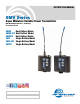

Super-Minature Belt Pack Transmitter
Rio Rancho, NM
5
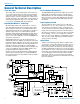
Signal Encoding and Pilot Tone
In addition to controlling the limiter, the DSP also en-
codes the digitized audio from the A/D converter and
adds an ultrasonic pilot tone to control the squelch in
the receiver. A pilot tone squelch system provides a reli-
able method of keeping a receiver output muted (audio
mute) even in the presence of significant interference.
When the system is operating in the Nu Hybrid mode
(available in US transmitters), a different pilot tone
frequency is generated for each carrier frequency to
prevent inadvertent squelch problems in multi-channel
sytems.
Microprocessor Control
A microprocessor monitors user command inputs from
the control panel buttons and numerous other internal
signals. It works intimately with the DSP to ensure the
audio is encoded according to the selected Compatibil-
ity Mode and that the correct pilot tone is added to the
encoded signal.
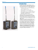
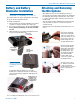
Control Panel
The control panel includes four membrane switches and
an LCD screen to adjust the operational settings. Multi-
color LEDs are used to indicate audio signal levels for
accurate gain adjustment and for battery status.
Wide-Band Deviation
±75 kHz deviation improves the signal to noise ratio and
audio dynamic range of a wireless system dramatically,
compared to other designs that use ±30 kHz to 40 kHz
deviation. Wide deviation combined with a high powered
transmitters makes a significant improvement in signal
to noise ratio and operating range.
Variable Power Output
This advanced feature allows the operator to optimize
the transmitter for maximum battery life, or for maximum
operating range. Power output is selected using the
LCD in a setup mode while the RF output of the trans-
mitter is turned off.
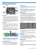
Battery Options and Operating Time
Switching power supplies convert regulated battery volt-
ages to operate various circuit stages with maximum
efficiency.
The firmware “remembers” the power status when a
battery fails, so the transmitter will be turned on auto-
matically when the battery is replaced and the previous
settings will be enabled.
Circulator/Isolator
The RF output circuit includes a one way circulator/iso-
lator using a magnetically polarized ferrite. This device
greatly reduces RF intermodulation produced when
multiple transmitters are used in close proximity to one
another (several feet apart). The isolator also provides
additional RF output stage protection against static
shock.