
User's Manual

SMWB Series
LECTROSONICS, INC.
18
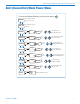
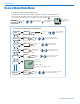
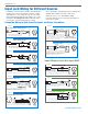
The wiring diagrams included in this section represent
the basic wiring necessary for the most common types
of microphones and other audio inputs. Some micro-
phones may require extra jumpers or a slight variation
on the diagrams shown.
It is virtually impossible to keep completely up to date
on changes that other manufacturers make to their
products, thus you may encounter a microphone that
differs from these instructions. If this occurs please call
our toll-free number listed under Service and Repair in
this manual or visit our web site at:
www.lectrosonics.com
10k
1k
5
4
3
2
1
To Audio Amplifier
5V SOURCE
MIC
VOLTAGE SELECT
LINE IN
GND
+
15uF
+5 VDC
Servo Bias
Pin 4 to Pin 1 = 0 V
Pin 4 Open = 2 V
Pin 4 to Pin 2 = 4 V
+
To Limiter Control
30uF
500 Ohm
100 Ohm
2.7K
200 Ohm
+
3.3uF
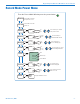
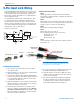
5-Pin Input Jack Wiring
Audio input jack wiring:
PIN 1
Shield (ground) for positive biased electret lavaliere
microphones. Shield (ground) for dynamic microphones
and line level inputs.
PIN 2
Bias voltage source for positive biased electret lavaliere
microphones that are not using servo bias circuitry and
voltage source for 4 volt servo bias wiring.
PIN 3
Microphone level input and bias supply.
PIN 4
Bias voltage selector for Pin 3.
Pin 3 voltage depends on Pin 4 connection.
Pin 4 tied to Pin 1: 0 V
Pin 4 Open: 2 V
Pin 4 to Pin 2: 4 V
PIN 5
Line level input for tape decks, mixer outputs, musical
instruments, etc.
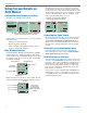
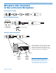
Installing the Connector:
1) If necessary, remove the old connector from the
microphone cable.
2) Slide the dust boot onto microphone cable with the
large end facing the connector.
3) If necessary, slide the 1/8-inch black shrink tubing
onto the mircrophone cable. This tubing is needed
for some smaller diameter cables to ensure there
is a snug fit in the dust boot.
4) Slide the backshell over the cable as shown above.
Slide the insulator over the cable before soldering
the wires to the pins on the insert.
5) Solder the wires and resistors to the pins on the
insert according to the diagrams shown in Wiring
Hookups for Different Sources. A length of .065
OD clear tubing is included if you need to insulate
the resistor leads or shield wire.
6) If necessary, remove the rubber strain relief from
the TA5F backshell by simply pulling it out.
7) Seat the insulator on the insert. Slide the cable
clamp over the and of the insulator and crimp as
shown on the next page.
8) Insert the assembled insert/insulator/clamp into
the latchlock. Make sure the tab and slot align
to allow the insert to fully seat in the latchlock.
Thread the backshell onto the latchlock.
TA5F Latchlock
Insert
Insulator
Cable clamp
Backshell with
strain relief
Remove strain relief
if using dust boot
Backshell
without strain
relief
Dust boot (35510)
Note: If you use the dust boot, remove the rubber
strain relief that is attached to the TA5F cap, or the
boot will not fit over the assembly.