
User's Manual

SMWB Series
LECTROSONICS, INC.
20
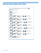
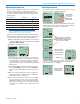
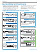
Compatible Wiring for Both Servo Bias Inputs and Earlier Transmitters:
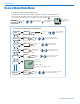
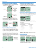
Simple Wiring for Servo Bias Inputs ONLY:
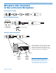
Input Jack Wiring for Different Sources
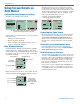
In addition to the microphone and line level wiring illus-
trated below, Lectrosonics makes a number of cables
and adapters for other situations such as connecting
musical instruments (guitars, bass guitars, etc.) to the
transmitter. Visit www.lectrosonics.com and click on
Accessories, or download the master catalog.
A lot of information regarding microphone wiring is also
available in the FAQ section of the web site at:
www.lectrosonics.com > SUPPORT > FAQs
Follow the instructions to search by model number or
other search options.
4 VOLT POSITIVE BIAS 2-WIRE ELECTRET
Most common type of wiring for lavaliere mics.
Fully compatible with 5-pin inputs on Lectrosonics
transmitters such as the LM and UM Series.
Fig. 2
SHIELD
TIP
PIN
5
4
3
2
1
SLEEVE
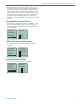
LINE LEVEL
RCA or 1/4” PLUG
A UDI O
1
2
3
4
5
T A5 F
PLUG
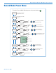
UNBALANCED LINE LEVEL SIGNALS
For signal levels up to 3V (+12 dBu) before limiting. Fully
compatible with 5-pin inputs on other Lectrosonics transmitters
such as the LM and UM Series. A 20k ohm resistor can be
inserted in series with Pin 5 for an additional 20 dB of
attenuation to handle up to 30V (+32 dBu).
Fig. 8
1
2
3
4
5
PIN
SHIELD
AUDIO
1
2
3
4
5
T A5 F
PLUG
2.7 k
2 VOLT NEGATIVE BIAS 2-WIRE ELECTRET
Compatible wiring for microphones
such as negative bias TRAM models.
NOTE: The resistor value can range from 2k to 4k ohms.
Fig. 4
DRAIN (BIAS)
SOURCE (AUDIO)
SHIELD
4 VOLT POSITIVE BIAS 3-WIRE ELECTRET
WITH EXTERNAL RESISTOR
This wiring is fully compatible with 5-pin inputs on Lectrosonics
transmitters such as the LM and UM Series. This is the wiring
for the Lectrosonics M152 lavaliere microphone.
Used for 3-wire lavaliere
microphones that require an
external resistor such as the
Sanken COS-11.
Fig. 5
Fig. 3
DPA MICROPHONES (Danish Pro Audio miniature models)
This wiring is for DPA lavalier
and headset microphones.
NOTE: The resistor value can range from 3k to 4k ohms.
Fig. 10
2 VOLT NEGATIVE BIAS 2-WIRE ELECTRET
Simplified wir
ing for microphones such as negative bias TRAM.
NOTE: This Servo Bias wiring is not compatible with earlier
versions of Lectrosonics transmitters. Check with the factory
to confirm which models can use this wiring.
Fig. 6
LO-Z MICROPHONE LEVEL SIGNALS
For low impedance dynamic mics or electret
mics with internal battery or power supply.
XLR JACK
Insert 1k resistor in series with pin 3 if attenuation is needed
4 VOLT POSITIVE BIAS 3-WIRE ELECTRET
NOTE: This Servo Bias wiring is not compatible with earlier
versions of Lectrosonics transmitters. Check with the factory
to confirm which models can use this wiring.
Fig. 11
1
2
3
4
5
PIN
SHIELD
A UDI O
1
2
3
4
5
T A5 F
PLUG
3.3 k
1.5 k
2 VOLT POSITIVE BIAS 2-WIRE ELECTRET
Compatible wiring for microphones such as
Countryman E6 headworn and B6 lavaliere.
Fig. 1
2 VOLT POSITIVE BIAS 2-WIRE ELECTRET
Simplified wiring for microphones
such as Countryman B6 Lavalier
and E6 Earset models and others.
NOTE: This Servo Bias wiring is not compatible with earlier
versions of Lectrosonics transmitters. Check with the factory
to confirm which models can use this wiring.
Fig. 9
SHIELD
TIP
PIN
5
4
3
2
1
SLEEVE
LINE LEVEL
RCA or 1/4” PLUG
A UDI O
1
2
3
4
5
T A5 F
PLUG
UNBALANCED LINE LEVEL SIGNALS
For signal levels up to 3V (+12 dBu) before limiting. Fully
compatible with 5-pin inputs on other Lectrosonics transmitters
such as the LM and UM Series. A 20k ohm resistor can be
inserted in series with Pin 5 for an additional 20 dB of
attenuation to handle up to 30V (+32 dBu).
Fig. 8
See Line Level
Signals on next page