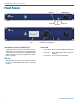
INSTALLATION and STARTUP GUIDE SPN16i/SPN32i Input Only Processors 16i 32i See Quick Start Essential Settings on page 5 Visit the ASPEN Support web site: www.lectrosonics.com/aspensupport/ Also link from the home page: www.lectrosonics.com Fill in for your records: Serial Number: Purchase Date: Rio Rancho, NM, USA www.lectrosonics.
ASPEN Input Only Processors 2 LECTROSONICS, INC.
Installation and Startup Guide Important Safety Instructions This symbol, wherever it appears, alerts you to the presence of uninsulated dangerous voltage inside the enclosure -- voltage that may be sufficient to constitute a risk of shock. This symbol, wherever it appears, alerts you to important operating and maintenance instructions in the accompanying literature. Please read the manual.
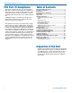
ASPEN Input Only Processors FCC Part 15 Compliance Table of Contents CAUTION: Changes or modifications not expressly approved by Lectrosonics, Inc. could void the user’s authority to operate the equipment. Important Safety Instructions............................................. 3 Inspection of the Unit........................................................... 4 Introduction........................................................................... 5 Quick Start Essential Settings.....................
Installation and Startup Guide Introduction The SPN16i and SPN32i processors are used as a Slaves in a stack of ASPEN processors. There are no physical outputs on these “input only” processors. As their descriptions imply, the only outputs are into the system matrix that is common to all processors in the stack. The ASPEN digital matrix provides a maximum of 48 total outputs, but there is no limit to the number of inputs that can be added to a system by stacking multiple units.
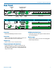
ASPEN Input Only Processors Front Panels USB Port POWER Switch 16i SPN16i Comm LED Alert LED Power LED 32i SPN32i LCD LCD and Rotary Encoder (SPN32i only) Backlit display shows activity and setup screens for adjustment of all settings. Rotary encoder includes a “center switch” for item selection. UP, DOWN, LEFT, RIGHT switches are used for navigation and adjustments of settings.
Installation and Startup Guide Rear Panel SPN16i chassis (rear panel) P/N 26058 silkscreening 8 Dec 2009 BCJ added label placement markers 24 May 2012 BCJ added CE mark Cooling Fan Outlet Programmable Input and Output Ports SPN 16i GND PROG IN INPUTS DATECODE +5V PROG OUT S/N LABEL 100-240V 50/60Hz 15W RS-232 Power Inlet SPN 32i ASPEN PORT ETHERNET RS232 Serial Port Ethernet Port ASPEN Ports Mic/Line Inputs GND PROG IN DATECODE INPUTS +5V PROG OUT 17 18 19 20 21 22 23 24
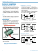
ASPEN Input Only Processors Hardware Installation It is recommended to use lacing bars for cable strain relief when mounting in a rack. Use only professional audio cable with proper shielding – typically, two conductor plus ground/shield. Retaining Screw (Do not overtighten) Two wire cables should have a jumper between the processor (–) input and ground. Source Caution: Do not overtighten the screws. 5-pin depluggable connector Do not leave more than 1 mm of exposed wire beyond the connector.
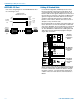
Installation and Startup Guide Programmable Inputs Programmable Outputs Programmable inputs are provided to enable external control over a variety of parameters. Each input can respond to a contact closure, a DC voltage source, or the variable voltage output from a potentiometer. The following illustrates common connections to the programmable input pins.
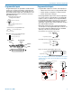
ASPEN Input Only Processors ASPEN RS-232 Port Cabling Of Stacked Units Here is the wiring diagram for the ASPEN RS-232 Port for connecting to a PC. Wiring Diagram ASPEN Device to PC 1 TX 2 RX 3 ASPEN 4 RS-232 GND 5 Port 6 7 8 9 DCE pin functions Female jack 1 2 3 4 5 6 7 8 9 DCD RX TX DTR GND DSR RTS CTS RI Host Serial Port (PC) DTE pin functions Male jack Male connector In a stacked configuration, ASPEN processors must be interconnected as shown here.
Installation and Startup Guide Using the LCD Shortcut Buttons The LCD can be used to perform a simple setup, to check current settings or make adjustments without using a computer interface. • LCD Backlight Toggle: Press both the LEFT and RIGHT (9:00 and 3:00 o’clock) buttons to turn the backlight on and off. • Emergency Mute (panic button): Pressing the UP and DOWN buttons together will mute all outputs to remedy situations such as runaway feedback.
ASPEN Input Only Processors After selecting the mode and/or changing the passcode, select SAVE with the rotary control and press the center switch to save the settings. Select Mic/Line Input Setup (Input Levels is a dymanic display that shows bar graphs of activity). A progress bar will appear as the settings are saved. Press the LEFT (9:00 o’clock) button to return to the previous screen. Master Reset Hold the LEFT and UP buttons in at power up to restore factory default settings.
Installation and Startup Guide Adjust to the desired value with the rotary control and press the control to store the value. (the Crosspoint Gain setting screen is shown here as an example) Global System Settings Select [SYS] in the Main Window to access a setup menu for a variety of global settings including headphone monitoring, date and time setup, timer and event programming, front panel lockout, network interface settings and others.
ASPEN Input Only Processors Network Interface IMPORTANT: Always consult your network administrator before attempting to connect and configure a processor for a network interface. The [SYS] tab menu also includes Network Settings. Software and Firmware Updates Check for the latest versions of the control panel software and to see that the hardware includes the latest firmware.
Installation and Startup Guide Creating an ASPEN Installer Disk If you do not have the disk supplied with the processor, go to either of the following sites and download the ASPEN Installation Disk .iso file. http://www.lectrosonics.com/aspensupport/ Link from the home page: http://www.lectrosonics.com Save the file to your local drive in a familiar location. Open a disk copier utility such as Roxio Classic and select the operation to Burn from a Disk Image File. NOTE: The .
ASPEN Input Only Processors Software Installation NOTE: Uninstall previous version before installing the software. The example shown here illustrates the installation procedure using Windows XP. The screens that appear at each step using another operating system will vary, but the general steps are very similar. Insert the disk into the drive and wait for the opening screen to appear. Click on Install ASPEN Software to launch the installer.
Installation and Startup Guide USB Driver Installation The ASPEN USB drivers are installed from the ASPEN Installation Disk which comes with each device, by running the ASPEN Device Installer. Normally this is done before connecting an ASPEN device to the PC for the first time, but it can be done afterwards if necessary. The driver installation only needs to be done once on each PC that will be connected to an ASPEN unit.
ASPEN Input Only Processors Using the Software GUI for Minimum Setup Define inputs, crosspoints and outputs on the appropriate tabs for a required minimum setup. An Input, crosspoint and output must be defined to create a path that allows the processor to pass a signal. This required minimum setup can be accomplished quickly using the sofware GUI. Launch the ASPEN Control Panel. The first screen is blank with tabs at the top of the window to select the desired action.
Installation and Startup Guide Service and Repair If your system malfunctions, you should attempt to correct or isolate the trouble before concluding that the equipment needs repair. Make sure you have followed the setup procedure and operating instructions. Check the interconnecting cables and then go through the Troubleshooting section in this manual.
ASPEN Input Only Processors LIMITED THREE YEAR WARRANTY The equipment is warranted for three years from date of purchase against defects in materials or workmanship provided it was purchased from an authorized dealer. This warranty does not cover equipment which has been abused or damaged by careless handling or shipping. This warranty does not apply to used or demonstrator equipment. Should any defect develop, Lectrosonics, Inc.