INSTALLATION and STARTUP GUIDE SPNCWB Digital Conference Interface Hardware and Software Installation and Setup IMPORTANT See page 16 for Minimum Setup Requirements Visit the ASPEN Support web site: www.lectrosonics.com/aspensupport/ Also link from the home page: www.lectrosonics.com Fill in for your records: Serial Number: Purchase Date: Rio Rancho, NM, USA www.lectrosonics.
SPNCWB 2 LECTROSONICS, INC.
Installation and Startup Guide Important Safety Instructions This symbol, wherever it appears, alerts you to the presence of uninsulated dangerous voltage inside the enclosure -- voltage that may be sufficient to constitute a risk of shock. This symbol, wherever it appears, alerts you to important operating and maintenance instructions in the accompanying literature. Please read the manual.
SPNCWB 4 LECTROSONICS, INC.
Installation and Startup Guide Table of Contents Important Safety Instructions.................................................3 Introduction...............................................................................5 Inspection of the Unit...............................................................5 Controls and Features.............................................................6 Front Panel..............................................................................6 Rear Panel.................
SPNCWB Controls and Features Front Panel Headphone Monitor USB Port MCU Recovery recessed pushbutton Comm LED Alert LED Power LED POWER Switch Firmware Update recessed pushbutton Headphone Monitor Firmware Update (recessed pushbutton) Standard 1/4 inch jack and level control. Drives both channels of stereo headphones. MCU Recovery (recessed pushbutton) Used in the procedure to recover from an interrupted firmware update procedure. See section on Firmware Update Procedure for details on usage.
Installation and Startup Guide Rear Panel Cooling Fan Outlet Programmable Input and Output Ports SPNCWB GND PROG IN +5V RC 2 PROG OUT REMOTE CONTROL POWER AMP OUTPUTS 1 2 LINE OUTPUTS LINE INPUTS CODEC CODEC CODEC CODEC 2 1 2 1 TELEPHONE SET RC 1 100-240V 50/60Hz 35W Power Inlet RS-232 ETHERNET RS232 Serial Port Ethernet Port LINE Made In the USA DATECODE S/N LABEL ASPEN PORT Data/Audio Bus Ports Programmable Input and Output Ports Programmable inputs and outputs used to control
SPNCWB Hardware Installation It is recommended that you use lacing bars for cable strain relief when mounting in a rack. Use only professional audio cable with proper shielding – typically, two conductor plus ground/shield. Retaining Screw (Do not overtighten) Two wire cables should have a jumper between the processor (–) input and ground. Source Caution: Do not overtighten the screws. 5-pin depluggable connector Do not leave more than 1 mm of exposed wire beyond the connector.
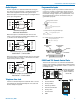
Installation and Startup Guide Programmable Inputs Audio Outputs The line outputs are a balanced differential configuration which can drive balanced or unbalanced inputs on other audio equipment with the wiring shown here. Shield Destination Output Balanced output to a balanced input is a straightforward “pin to pin” configuration. Programmable inputs are provided to enable external control over a variety of parameters.
SPNCWB Programmable Outputs LED is ON when the programmable output is active +5VDC Programmable outputs are used for several purposes: • indicate the current state of a programmable input • monitor activity on telephone or codec interfaces • monitor active preset changes 380 Ohms Programmable Output Pin LED is OFF when the programmable output is active Each programmable output is the electrical equivalent of a contact closure to ground.
Installation and Startup Guide ASPEN RS-232 Port Connecting the Master for the First Time Here is the wiring diagram for the ASPEN RS-232 Port for connecting to a PC.
SPNCWB Software Installation NOTE: Uninstall any previous version before installing the software. ASPEN Control Panel software can be installed from the disk supplied with each processor, or from files downloaded from the ASPEN Support web site. The third screen displays an option to select the desired installation. It is best to check all three boxes so the the USB driver, Control Panel and Help utility will all be installed. http://www.lectrosonics.
Installation and Startup Guide Software and Firmware Updates On ASPEN models with a front panel LCD, the firmware version is displayed on the Main menu screen. For all ASPEN models, the firmware version is displayed in the Control Panel program when connected to the processor. Creating an ASPEN Installer Disk If you do not have the disk supplied with the processor, go to the following site and download the ASPEN Installation Disk .iso file. http://www.lectrosonics.com/aspensupport/index.
SPNCWB Firmware Update Procedure 4) Update Procedure 1) It is assumed that the USB drivers and ASPEN control panel software have been installed. If not, go the the web site and download the Control Panel Installer and follow the instructions to install the USB driver, GUI and Help file. Connect the processor to the computer with the USB cable. 5) Click on Next in the control panel and another page will open, allowing you to select the device to be updated.
Installation and Startup Guide MCU Recovery from Interrupted Firmware Update Procedure If instructed to do so by Lectrosonics Customer Support, the firmware in a non-functioning unit can be restored. Launch the Control Panel program. After the panel opens, click on Connect->Update Firmware... In the lower part of the screen is a check box that is used only for the recovery process. When the box is checked, the instructions will change to describe the recovery procedure.
SPNCWB Minimum Setup A required minimum setup is needed to allow the processor to pass signals and provide acoustic echo cancellation: • Define the Inputs and adjust gain • Define the Crosspoints • Define the mixes to be used as signal sources for the outputs • Define the Outputs and adjust levels • Configure the Conferencing Connections Output Sources Click on the Output Source tab. These assignments pass the matrix mixes to the outputs.
Installation and Startup Guide Acoustic Echo Canceller Click on the Acoustic Echo Canceller tab at the bottom of the conferencing screen. The AEC (acoustic echo canceller) can be enabled on any or all of the conference interfaces. Strip chart metering indicates the performance of the AEC on each interface. Select the desired interface to display, or to display all four simultaneously.
The Signal Flow Screen Select the Signal Flow tab. This comprehensive, intuitive interface allows settings to be made through the entire signal chain. Double left click and single right click actions open setup and status dialogue boxes. 18 The view may be panned or zoomed as needed. Hold down the CTRL key and press + to zoom in. Hold down the CTRL key and press - to zoom out. The mouse scroll wheel can also be used. Hold down the CTRL key and turn the mouse wheel up or down to zoom in or out.
Unused crosspoint columns can be hidden and unhidden by highlighting a range of Mixes across the top, followed by a right click and selection of the desired state.
Network Setup The SPNCWB is IP addressable over an ordinary Ethernet network. The use of DHCP to configure the network interface is recommended for easy setup. Using the control panel software, navigate to DeviceSettings>Network and check the DHCP box. Connect the processor into the network and cycle the power. The processor will boot up and the DHCP server will assign an IP address. The address can be viewed in the Network window.
Stacking Multiple Units If Slave units are not powered up when the Master unit boots up, the Slave may not be detected for several minutes. It is good practice to turn all units on simultaneously or turn on Slave units before turning on the Master unit. The available processors will appear in a “stack” in the control panel. The Master unit details will appear at the top, with Slave units below it appearing in the order that they are connected with the cable connections to the ASPEN port jacks.
SPNCWB Service and Repair If your system malfunctions, you should attempt to correct or isolate the trouble before concluding that the equipment needs repair. Make sure you have followed the setup procedure and operating instructions. Check the interconnecting cables and then go through the Troubleshooting section in this manual. We strongly recommend that you do not try to repair the equipment yourself and do not have the local repair shop attempt anything other than the simplest repair.
Installation and Startup Guide FCC PART 15 COMPLIANCE INFORMATION This equipment has been tested and found to comply with the limits for a Class A digital device, pursuant to Part 15 of the FCC Rules. These limits are designed to provide reasonable protection against harmful interference when the equipment is operated in a commercial environment.
LIMITED THREE YEAR WARRANTY The equipment is warranted for three years from date of purchase against defects in materials or workmanship provided it was purchased from an authorized dealer. This warranty does not cover equipment which has been abused or damaged by careless handling or shipping. This warranty does not apply to used or demonstrator equipment. Should any defect develop, Lectrosonics, Inc. will, at our option, repair or replace any defective parts without charge for either parts or labor.