
User Manual


Installation and Startup Guide
Rio Rancho, NM
5
Introduction
The SPNCWB interface combines the audio from a
telephone line, two codecs and microphones in the lo-
cal sound system to provide natural sounding telepres-
ence and audio conference meetings. A powerful AEC
(acoustic echo canceller) is provided, which converges
fast enough to follow multi-site bridging and gain pro-
portional automatic mixing without losing convergence
depth. The AEC can handle an unlimited number of mi-
crophones and will re-converge quickly enough to follow
the movement of a wireless microphone.
Three sites can be bridged into a single conference with
one SPNCWB processor. Three additional sites can be
added with another processor with signals combined
into the ASPEN matrix for extensive routing and pro-
cessing options.
The outstanding performance of the AEC is further en-
hanced with patented, seamless automatic mixing. The
automatic mixing is applied at the crosspoints in the
matrix, which allows each signal source to exhibit a dif-
ferent behavior at the system outputs. This is useful, for
example, when the signal must participate in the confer-
ence using one of several automatic mixing modes on
some outputs, and be recorded with no processing on
other outputs.
For convenience, a TCP/IP addressable Ethernet port
and built in power amplifier are included.
This manual covers hardware installation and wir-
ing and the installation of ASPEN software. Once the
processor is communicating with a computer, refer to
the Help files in the software control panel for additional
setup and configuration settings.
Inspection of the Unit
Compare the packing list enclosed with the unit with
the original order. Inspect all items for damage. Im-
mediately call 1-800-821-1121 to report any items that
are missing or damaged. The sooner you notify us,
the sooner you will get any needed replacement items
shipped to your location.
*Crestron
®
is a registered trademark
of Crestron Electronics, Inc.
Table of Contents
Important Safety Instructions.................................................3
Introduction ..............................................................................5
Inspection of the Unit ..............................................................5
Controls and Features ............................................................6
Front Panel .............................................................................6
Rear Panel .............................................................................7
Hardware Installation ..............................................................8
Installing the chassis into a rack ............................................8
Cables ...................................................................................8
Audio Connectors .................................................................8
Audio Inputs – Unbalanced ....................................................8
Audio Inputs – Balanced ........................................................8
Audio Outputs ........................................................................9
Telephone Line Jack ..............................................................9
Programmable Inputs ............................................................. 9
CODEC and TEL Remote Control Ports ................................9
Power Amp Outputs .............................................................10
Programmable Outputs ........................................................10
ASPEN RS-232 Port ............................................................11
Connecting the Master for the First Time .............................11
Cabling Of Stacked Units .....................................................11
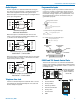
Software Installation .............................................................12
Using the Control Panel ........................................................12
Software and Firmware Updates ..........................................13
Creating an ASPEN Installer Disk ........................................13
Firmware Update Procedure .................................................14
Update Procedure ................................................................ 14
MCU Recovery from Interrupted Firmware Update .............15
Minimum Setup ......................................................................16
The Signal Flow Screen ........................................................18
Network Setup .......................................................................20
Web Browser Interface ..........................................................20
Stacking Multiple Units .........................................................21
Refer to the Help Files ...........................................................21
Service and Repair ................................................................22
Returning Units for Repair ...................................................22
FCC PART 68 COMPLIANCE INFORMATION .......................23
INDUSTRY CANADA NOTICE ...............................................23