INSTRUCTION MANUAL SRc5P & SRc Camera Slot Dual UHF Receiver Featuring Digital Hybrid Wireless® Technology U.S. Patent 7,225,135 Quick Start Summary The following checklist includes the minimum required settings to start using the receiver. • Install either a battery sled, camera slot adapter or other power source (see pages 9-13). • Set transmitters on the matching frequencies (see transmitter manual). • Connect power to the receiver (see pages 11, 12, 15).
SRc5P and SRc Dual Receivers 2
UHF Digital Hybrid Wireless® Table of Contents Wideband Tuning Range.........................................................4 Model Differences....................................................................4 SRc........................................................................................4 SRc5P....................................................................................4 General Technical Description...............................................5 Front Panel Controls and Functions.
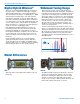
SRc5P and SRc Dual Receivers Digital Hybrid Wireless® The Lectrosonics Digital Hybrid Wireless® uses innovative technology to combine the advantages of digital audio with the advantages of analog RF transmission. The result delivers the superior sound quality of a digital system and the excellent range of an analog system. A proprietary algorithm encodes the digital audio information into an analog format which can be transmitted in a robust manner over an analog FM wireless link.
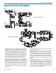
UHF Digital Hybrid Wireless® General Technical Description BPF LNA IF amp Mixer Tracking Tracking LNA Receiver 1 Splitter 248.450 MHz IF amp 350 kHz SAW filter SAW filter µP Phase combiner 1st VCO High side injection Phase combiner Splitter LNA BPF LNA Tracking Audio 1 Window detect 2nd VCO RSSI RF PCB Block Diagram PLL SRC Dual Receiver RF Board Ref.
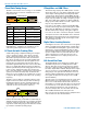
SRc5P and SRc Dual Receivers Three Block Tuning Range IF Amplifiers and SAW Filters The SRc receiver tunes across a range of over 76 MHz. This tuning range covers three standard Lectrosonics frequency blocks. TUNING RANGE BLOCK BLOCK BLOCK Tuning ranges are available covering standard blocks as follows: Band Blocks Covered Freq. (MHz) A1 470, 19, 20 470.100 - 537.575 B1 21, 22 23 537.600 - 614.375 B2 22, 23, 24 563.200 - 639.975 Block 606 23, 24 606.000 - 631.500 C1 24, 25, 26 614.
UHF Digital Hybrid Wireless® SmartSquelch™ A DSP-based algorithm called SmartSquelchTM optimizes the receiver performance in very weak signal conditions. The RF level and supersonic noise in the audio are continuously monitored to determine the appropriate noise reduction needed and the point at which squelch (complete muting of the audio) is necessary.
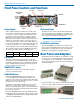
SRc5P and SRc Dual Receivers Front Panel Controls and Functions Receiver 1 Receiver 2 MENU/SELECT Button UP Button Secondary Audio Output DOWN Button Audio Outputs IR Sync Port POWER/BACK Button IR (Infrared) Sync Audio outputs and the power inlet are located on the rear panel, accessed by a variety of different adapters. A second set of audio outputs is provided next to the front panel on the “5P” version for use with cameras that have only one audio channel enabled in the slot.
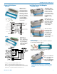
UHF Digital Hybrid Wireless® Camera Slot Adapters Installing Camera Slot Adapters SRSUPER SRSUPER Adapter Adapter kit for Unislot® camera slots such as those provided on Ikegami® and Panasonic® cameras, as well as the SL-6 by Sound Devices®.* Includes bezel, hardware and rear panel DB25 connector wired for power and audio connections.
SRc5P and SRc Dual Receivers Adapters for Stand-Alone Use SREXT For stand-alone use, this kit includes a rear panel with two TA3 male jacks for the balanced outputs and a power jack with a locking connector. Trim the power cable to the desired length. Installing Rear Panel Adapters Installation of the rear panel output/power adapters is the same for all models. Panels are held in place by two phillips head screws on the sides of the housing.
UHF Digital Hybrid Wireless® Battery Adapters Installing the SRBATTSLED Battery sled adapters configure the receiver for standalone use or to provide battery backup power. Several options are available: Orient the battery sled so that the PCB connectors will mate when the sled is inserted.
SRc5P and SRc Dual Receivers SR9VBP 9 Volt Battery Adapter This optional adapter is mounted onto the battery sled for use as the primary power source or as a battery backup for an external power supply. The housing and door are constructed of machined aluminum. Slide the latch plate in the center of the door outward and swing the door open for access to two 9 volt battery compartments. Polarity barriers in each battery compartment protect against inserting the battery backwards.
UHF Digital Hybrid Wireless® Attach the bracket to the sleeve with the long pan head screw into the standard pressnut. The retaining pin fits into the opening in the bracket. Attach the cold shoe mounting foot to the tensioning nut and rotate it to orient the receiver as desired.
SRc5P and SRc Dual Receivers Audio Output Cables and Connectors MCSR5PXLR5P Right angle TA5F plug to 5-pin XLR; balanced outputs; 25 inches long. For TA5M output jacks. External Power Supply DCR15/4AU Power supply with a standard C14 inlet and locking LZR coaxial output connector; 100-240 VAC in, 15 VDC regulated output; 4A max. MCSR5PXLR2 Right angle TA5F plug to two 3-pin XLR; balanced outputs; 20 inches long. For TA5M output jacks.
UHF Digital Hybrid Wireless® 21425 6 ft. long power cord; coaxial to stripped & tinned leads. Coaxial plug: ID-.080”; OD-.218”; Depth- .5”. ” .475 . ” O.D .375 21472 6 ft. long power cord; coaxial to stripped & tinned leads. Right angle coaxial plug: ID-.075”; OD-.218”; Depth.375” .375” .35” . ” O.D .375 21586 DC16A Pigtail power cable, LZR stripped & tinned. Thread lock collar.
SRc5P and SRc Dual Receivers Mounting and Orientation A variety of accessories are available to enable various mounting options. For maximum operating range, the antennas should be vertical and above the camera and other equipment. The AMJ Rev. A antenna is jointed so the whips can be oriented vertically.
UHF Digital Hybrid Wireless® AMJ Rev. A Jointed Antenna The AMJ antenna is a general purpose design for any Lectrosonics receiver or transmitter with a standard SMA connector. The hinged joint pivots in both directions for positioning the whip at any desired angle.
SRc5P and SRc Dual Receivers LCD Main Window Receiver 1 Receiver 2 RF Levels Diversity Activity Audio Level Pilot Tone Indicator The Main Window displays information concerning the condition of the Pilot Tone, antenna phase, RF and audio signal levels and battery conditions for both the receiver and the associated transmitter.
UHF Digital Hybrid Wireless® Main Window The appearance of the LCD Main Window will change according to which diversity mode is selected: • SWITCH (2-channel mode) splits the screen to indicate activity and levels on both receivers and transmitters. • RATIO combines the audio outputs of both receivers to deliver a single audio channel. With the DIV MODE set to SWITCH, two audio channels will be displayed. With the DIV MODE set to RATIO, a single audio channel will be displayed.
SRc5P and SRc Dual Receivers Navigating the LCD Receiver 1 Pilot Tone ON\OFF Hold MENU and press UP momentarily Receiver 2 Pilot Tone ON/OFF Hold MENU and press DOWN momentarily Main Window BACK Switched BACK MENU BACK MENU Mute Audio on Receiver 1 Hold MENU and hold DOWN Mute Audio on Receiver 2 MENU Setup Screen SETUP (item) Hold MENU and hold UP Ratio When DIVMODE is set to RATIO the frequency screen will look like this. Ratio Block Freq hex code Mode 1 26 : 80 Receiver 1 652.
UHF Digital Hybrid Wireless® Menu Item Descriptions LEVEL This setup screen displays the audio output level of the receiver in dBu when the transmitter is fully modulated. Press the MENU/SEL button to toggle between receiver 1 and receiver 2. Use the UP or DOWN buttons to change the level. Range is from -50 to +5 dBu in 1 dB steps. Press the BACK button to leave this screen.
SRc5P and SRc Dual Receivers TUNING In addition to the NOR (normal) mode, this screen also allows Selection of one of four factory pre-selected frequency groups (Groups a through d) or two user programmable frequency groups (Groups u and v). • NOR allows selection of all 256 frequencies that the receiver will tune. Each press of the UP or DOWN button will step in 100 kHz increments to the next frequency. • a, b, c, d sets the receiver to tune only factory preselected frequencies, up to eight in each group.
UHF Digital Hybrid Wireless® PHASE This setup screen allows the audio output polarity to be inverted to match other microphones or audio sources. TXBAT • AA - Transmitter uses a AA alkaline battery. • AAL - Transmitter uses a AA lithium battery (not rechargeable). • AAT - Transmitter uses an alkaline, lithium or rechargeable AA battery. Monitor the battery status with the timer in the receiver. • LB - Transmitter uses a Lectrosonics LB-50 rechargeable battery.
SRc5P and SRc Dual Receivers Finding Clear Frequencies with SmartTuneTM SmartTune is the easiest and fastest way to scan the local RF spectrum and find clear operating frequencies. The receiver will scan through its tuning bandwidth and automatically find “empty” areas within the tuning range that have little or no RF energy. The receiver will then be set to a frequency within an empty area and prompt you to continue or use the IR function to sync to a transmitter.
UHF Digital Hybrid Wireless® Finding Clear Frequencies with Manual Scanning Scan Window Receiver 1, dashed line Zoom View Window Receiver 2, solid line Block 26 BD RF activity level Freq in hex Cursors blink to indicate the currently selected receiver Cursor (center bar) Block 25 C7 Press both UP and DOWN arrows on control panel to switch to the Zoom View Press the BACK button to return to the Scan View Window First, turn off all of the transmitters you intend to use with the receiver.
SRc5P and SRc Dual Receivers Pre-coordinated Frequencies NOTE: As the spectrum has become more congested, interference from external sources has become common. As a result, the frequencies provided in these pre-coordinated groups may or may not be 100% usable in some locations. Interference from external sources may appear as direct signals, or may mix with the pre-coordinated frequencies and generate new RF signals through IM (intermodulation).
UHF Digital Hybrid Wireless® Frequency Coordination IM (intermodulation) is a process of two or more RF signals mixing in any stage in the transmitter or receiver that generates another RF signal. If this new signal happens to land on a carrier, IF or oscillator frequency you may have interference problems that affect range or audio quality. The possible combinations also include odd and even order harmonics of the carriers. Feel free to contact the factory if you need help in coordinating frequencies.
SRc5P and SRc Dual Receivers Troubleshooting Symptom Possible Cause INITIAL POWER ON LCD display not active or lit External power supply disconnected or inadequate. Wrong polarity power source. The external power input jack requires POSITIVE (+) to be on the center pin. Battery gets warm and doesn’t work. Version message shows DSP or COM This indicates an internal error. Please contact the factory for assistance.
UHF Digital Hybrid Wireless® Symptom Possible Cause ANTENNAS AND RF SIGNAL STRENGTH RF Level is weak No RF Signal AUDIO SIGNAL QUALITY Poor signal-to-noise ratio Receiver may need to be moved or reoriented. Antenna on transmitter or receiver may be defective or poorly connected - double check antennas. Improper length of antenna, or wrong antenna on transmitter or receiver. UHF whip antennas are generally about 3 to 5 inches long.
SRc5P and SRc Dual Receivers Specifications and Features Operating Frequencies: Band A1: Band B1: Band B2: Block 606: Band C1: Band C2: 470.100 - 537.575 MHz 537.600 - 614.375 MHz 563.200 - 639.975 MHz 606.000 - 631.500 MHz 614.400 - 691.175 MHz 640.000 - 713.900 MHz/716.775 MHz selectable Frequency selection steps: Selectable; 100 kHz or 25 kHz Receiver Type: Dual conversion, superheterodyne IF Frequencies: Ch.1: 248.450 MHz and 350.000 kHz Ch. 2: 243.950 MHz and 250.
UHF Digital Hybrid Wireless® Service and Repair If your system malfunctions, you should attempt to correct or isolate the trouble before concluding that the equipment needs repair. Make sure you have followed the setup procedure and operating instructions. Check the interconnecting cables and then go through the Troubleshooting section in this manual.
SRc5P and SRc Dual Receivers Attestation of Conformity 32 LECTROSONICS, INC.
UHF Digital Hybrid Wireless® Declaration of Conformity Rio Rancho, NM 33
SRc5P and SRc Dual Receivers 34 LECTROSONICS, INC.
UHF Digital Hybrid Wireless® Rio Rancho, NM 35
LIMITED ONE YEAR WARRANTY The equipment is warranted for one year from date of purchase against defects in materials or workmanship provided it was purchased from an authorized dealer. This warranty does not cover equipment which has been abused or damaged by careless handling or shipping. This warranty does not apply to used or demonstrator equipment. Should any defect develop, Lectrosonics, Inc. will, at our option, repair or replace any defective parts without charge for either parts or labor.