
User's Manual


SRc5P and SRc Dual Receivers
LECTROSONICS, INC.
6
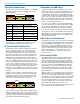
Three Block Tuning Range
The SRc receiver tunes across a range of over 76 MHz.
This tuning range covers three standard Lectrosonics
frequency blocks.
TUNING RANGE
BLOCK
BLOCK
BLOCK
Tuning ranges are available covering standard blocks as
follows:
Band Blocks Covered Freq. (MHz)
A1 470, 19, 20 470.100 - 537.575
B1 21, 22 23 537.600 - 614.375
B2 22, 23, 24 563.200 - 639.975
Block
606
23, 24
606.000 - 631.500
C1 24, 25, 26 614.400 - 691.175
C2 25, 26, 27 640.000 - 716.775
To simplify backward compatibility with earlier Digital
Hybrid Wireless
®
equipment, block numbers are pre-
sented along with frequencies in LCD screens.
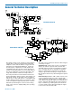
RF Front-End with Tracking Filter
A wide tuning range is helpful in finding clear frequen-
cies for operation, however, it also allows a greater
range of interfering frequencies to enter the receiver.
The UHF frequency band, where almost all wireless
microphone systems operate, is heavily populated by
high power TV transmissions. The TV signals are im-
mensely more powerful than a wireless microphone
transmitter signal and will enter the receiver even when
they are on significantly different frequencies than the
wireless system. This powerful energy appears as noise
to the receiver, and has the same effect as the noise
that occurs with extreme operating range of the wireless
system (noise bursts and dropouts). To alleviate this
interference, front-end filters are needed in the receiver
to suppress RF energy below and above the operating
frequency.
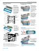
The SRc receiver employs a variable frequency, track-
ing filter in the front-end section (the first circuit stage
following the antenna). As the operating frequency is
changed, the filters re-tune in fine increments to stay
centered over the selected carrier frequency.
BLOCK
BLOCK
BLOCK
In the front-end circuitry, a tuned filter is followed by an
amplifier and then another filter to provide the selectivity
needed to suppress interference. This unique filter de-
sign allows a wide tuning range and retains the sensitiv-
ity needed for extended operating range.
IF Amplifiers and SAW Filters
The first IF stage employs two SAW (surface acoustic
wave) filters. The use of two filters significantly increas-
es the depth of filtering while preserving sharp skirts,
constant group delay, and narrow bandwidth. Though
expensive, this special type of filter allows primary filter-
ing as early as possible, at as high a frequency as pos-
sible, before high gain is applied, to deliver maximum
image rejection. These filters are made of quartz, and
they are very temperature stable.
In receiver 1, the signal is converted to 248.950 MHz
in the first mixer stage, then passed through two SAW
filters. After the SAW filters, the signal is converted to
350 kHz and then the majority of the gain is applied.
In receiver 2, the same conversions take place at differ-
ent frequencies: first to 243.950 MHz, then to 250 kHz.
Although these IF frequencies are unconventional in a
wide deviation (±75 kHz) system, the design provides
excellent image rejection.
Digital Pulse Counting Detector
Following the IF section, the receiver uses an elegantly
simple, yet highly effective digital pulse counting detec-
tor to demodulate the FM signal to generate the audio,
rather than a conventional quadrature detector. This
unusual design eliminates thermal drift, improves AM
rejection, and provides very low audio distortion. The
output of the detector is fed to the microprocessor
where a window detector is employed as part of the
squelch system.
DSP-Based Pilot Tone
The Digital Hybrid system design uses a DSP gener-
ated ultrasonic pilot tone to reliably mute the audio
when no RF carrier is present. The pilot tone must be
present in conjunction with a usable RF signal before
the audio output will be enabled. 256 pilot tone frequen-
cies are used across each 25.6 MHz block within the
tuning range of the system. This alleviates erroneous
squelch activity in multichannel systems where a pilot
tone signal can appear in the wrong receiver via IM
(intermodulation).
The pilot tones are repeated with each successive 25.6
MHz increment across the tuning range of units that
tune across a 3-block band. These units can tune in ei-
ther 25 kHz or 100 kHz steps. The pilot tones increment
in 100 kHz steps, so the pilot tone will be the same for
all four adjacent frequencies in each 100 kHz incre-
ment. For example, 550.100, 550.1256, 550.150 and
550.175 MHz will all have the same pilot tone.
Pilot tones are also provided for legacy equipment and
some models from other manufacturers.