
User's Manual


SRc5P and SRc Dual Receivers
LECTROSONICS, INC.
8
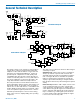
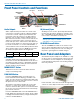
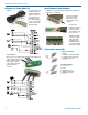
Front Panel Controls and Functions
Audio Outputs
Audio outputs and the power inlet are located on the
rear panel, accessed by a variety of different adapters.
A second set of audio outputs is provided next to the
front panel on the “5P” version for use with cameras
that have only one audio channel enabled in the slot.
One channel can feed the connector in the camera slot,
and the second channel can be connected to the ex-
ternal audio jack on the camera with a cable. When the
receiver is used outside of a camera, the 5-pin jack can
be used to feed audio to a recorder, IFB transmitter or
camera while the others feed the main production mixer.
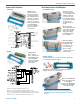
The front panel 5-pin connector (TA5M type) provides
two balanced outputs with the following pinouts:
Pin 1 Pin 2 Pin 3 Pin 4 Pin 5
Shields CH1 + CH1 – CH2 + CH2 –
LCD Screen
A backlit, graphics-type LCD is used to set up and
monitor the receiver. The Main Window shown above is
used during normal operation, to display RF and audio
levels, transmitter battery status, pilot tone status and
diversity activity for both receivers.
MENU/SELECT Button
This button is used to select menu items and enter
setup screens during setup.
PWR/BACK Button
Press the PWR/BACK switch to turn the power on.
Press and hold it until the display goes blank to turn
power off. It also functions as a “back” button while navi-
gating the various menus and setup screens to return to
the previous screen or menu item.
The firmware “remembers” whether the receiver was
turned on or off after power is disconnected, and it
returns to that state when power is restored. This allows
the receiver to power up and down as the external sup-
ply is turned on and off.
Press the PWR/BACK button from the Main Window to
briefly display the external power voltage. Press it again
to display the transmitter battery voltages. A third press
returns to the Main Window.
IR (Infrared) Sync
An IR Sync Port is used for quick setup with transmit-
ters that offer this feature. Settings for frequency, step
size, compatibility mode and talk back are transferred
from receiver to transmitter via the IR ports.
NOTE: Selected compatibility modes and talk back
will only sync if they are available options on the
transmitter you are syncing with.
UP/DOWN Arrow Buttons
The UP and DOWN arrow buttons are used to select
various options and adjust values in the setup screens,
and provide secondary functions such as locking out
the panel to guard against accidental changes.
Rear Panel and Adapters
Several different panel adapters are available to config-
ure the receiver for use with popular camera slots and
for stand-alone use. The adapters are retained by two
screws through the side panel of the housing, making
them easy to install.
Power and audio connections are made through mating
connectors on the adapter and receiver circuit boards.
DOWN Button
MENU/SELECT
Button
POWER/BACK
Button
UP Button
Receiver 1 Receiver 2
Secondary
Audio
Output
IR Sync Port