INSTRUCTION MANUAL SSM Digital Hybrid Wireless® Micro Transmitter SSM, SSM-941, SSM/E01, SSM/E01-B2, SSM/E02, SSM/E06, SSM/X Quick Start Steps 1) Install a good battery and turn power on (see pages 5 and 8). 2) Set the compatibility mode to match the receiver (see page 9). 3) Connect the signal source and adjust input gain for optimum modulation level (see page 10). 4) Set Step Size and frequency to match receiver (see pages 8 and 9).
SSM, SSM-941, SSM/E01, SSM/E02, SSM/E06, SSM/X 2 LECTROSONICS, INC.
Micro Body Pack Transmitter Table of Contents Quick Start Steps...................................................................................................................................................................................1 About Digital Hybrid Wireless®.............................................................................................................................................................................................................................................
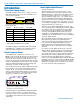
SSM, SSM-941, SSM/E01, SSM/E02, SSM/E06, SSM/X Introduction About Digital Hybrid Wireless® US Patent 7,225,135 Three Block Tuning Range The SSM transmitter tunes across a range of over 76 MHz. This tuning range covers three standard Lectrosonics frequency blocks. TUNING RANGE BLOCK BLOCK BLOCK Four tuning ranges are available covering standard blocks as follows: Range Blocks Covered Freq. MHz A1 470, 19, 20 470.1 - 537.5 B1 21, 22, 23 537.6 - 614.3 B2 22, 23, 24 563.2 - 639.
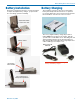
Micro Body Pack Transmitter Battery Installation The battery compartment and door catch are designed for simple and quick battery changes, yet prevent the door from being opened accidentally. Battery Charging The transmitter operates from a 3.6 V rechargeable battery that will provide about six hours of operation per charge. Battery life can be monitored from the timer function built into current Lectrosonics receivers.
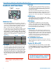
SSM, SSM-941, SSM/E01, SSM/E02, SSM/E06, SSM/X Controls and Functions Modulation LEDs BATT LED BATT LED This LED glows green when the battery is good. The color changes to red when there is only a few minutes of operation left. The LED will blink briefly, just before the unit powers down. The exact point at which the LED turns red will vary with battery brand and condition, temperature and current drain. The LED is intended to simply catch your attention, not to be an exact indicator of remaining time.
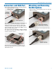
Micro Body Pack Transmitter Connectors and USB Port The housing is machined out of a solid aluminum billet for a rugged, lightweight assembly. Attaching and Removing the Microphone Align the ridges on the plug with the grooves in the jack and insert the plug. IR (infrared) port Galvanized steel flexible whip antenna Mic/Line input jack The antenna is a flexible whip made of galvanized steel, permanently attached to the transmitter to prevent damage from heavy use.
SSM, SSM-941, SSM/E01, SSM/E02, SSM/E06, SSM/X Operating Instructions Powering On in Operating Mode Press and hold the Power Button for several seconds until a counter on the LCD progresses from 1 through 3, followed by a display of the model, firmware version, frequency block and compatibility mode. Screens Used in Normal Operation When the transmitter is turned on with the RF output on, the LCD will display the frequency, audio gain or LF roll-off point. Audio gain is expressed in dB.
Micro Body Pack Transmitter Setup Steps The setup menus are accessed by holding either the UP or DOWN arrow while powering the unit on. Refer to Setup Screens on the next page for details of each setup parameter. The following list outlines the steps necessary to set up the transmitter for normal use. 1) Install a charged battery. 2) Set the compatibility mode to match the receiver to be used. 3) Adjust the step size and frequency to match the receiver.
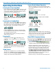
SSM, SSM-941, SSM/E01, SSM/E02, SSM/E06, SSM/X Setup Screens DOWN Button Menu Hold the DOWN button while powering up the unit. Then press the AUDIO button repeatedly to scroll through the following settings. Use the UP and DOWN arrows to select the available options under each setting.
Micro Body Pack Transmitter Microphone Wiring Looking into the 3 pin Lemo mic connector from the outside of the transmitter, the pin centered in the two guide slots is pin 1 (ground). Pin 2 is a 1k resistor to ground. Pin 3 is the audio/bias connection for two-wire microphones and line inputs.
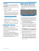
SSM, SSM-941, SSM/E01, SSM/E02, SSM/E06, SSM/X IR (infrared) Sync An IR (infrared) link between an associated receiver and the transmitter can be used to shorten setup time and ensure that the correct settings in the transmitter are made. The dome on the side panel of the transmitter is the port used for the IR link. The receiver is normally used to identify a clear operating frequency.
Micro Body Pack Transmitter LectroRM Android By New Endian LLC LectroRM is a mobile application for iOS and Android smart phone operating systems. Its purpose is to make changes to the settings on select Lectrosonics transmitters by delivering encoded audio tones to the microphone attached to the transmitter. When the tone enters the transmitter, it is decoded to make a change to a variety of different settings such as input gain, frequency and a number of others.
SSM, SSM-941, SSM/E01, SSM/E02, SSM/E06, SSM/X Accessories Rechargeable battery Antenna upward belt clip P/N 40106-1 LB-50 3.
Micro Body Pack Transmitter Firmware Update Updating the firmware is a simple matter of downloading a utility program and file from the website and running the program on a Windows operating system with the transmitter connected to a computer via the USB port. Step 2: Next, test the Updater by opening the icon: driver opens automatically, proceed to Step 3. If the WARNING: If you receive the following error, the Updater is not installed on your system. Follow the TROUBLESHOOTING steps to fix the error.
SSM, SSM-941, SSM/E01, SSM/E02, SSM/E06, SSM/X Step 3: Step 7: Refer to Step 1 to return to Firmware web page. Download Firmware Update and save to a local file on your PC for easy locating when updating. In Lectrosonics USB Firmware Updater, choose the detected device, browse to local Firmware File and click Start. NOTE: It may take up to a minute or so for the Updater to recognize the transmitter. WARNING: Do not disrupt the microUSB cable during updating.
Micro Body Pack Transmitter Specifications Operating Frequencies: SSM: Band A1: 470.100 - 537.575 Band B1: 537.600 - 607.950 SSM/E01: Band A1: 470.100 - 537.575 Band B1: 537.600 - 614.375 Band B2: 563.200 - 639.975 Block 606: 606.000 - 631.500 Band C1: 614.400 - 691.175 SSM/E01-B2: Band B2: 563.200 - 639.975 SSM/E02: Band A1: 470.100 - 537.575 Band B1: 537.600 - 614.375 Band B2: 563.200 - 639.975 Band C1: 614.400 - 691.175 Band C2: 640.000 - 716.
SSM, SSM-941, SSM/E01, SSM/E02, SSM/E06, SSM/X Service and Repair If your system malfunctions, you should attempt to correct or isolate the trouble before concluding that the equipment needs repair. Make sure you have followed the setup procedure and operating instructions. Check the interconnecting cables. We strongly recommend that you do not try to repair the equipment yourself and do not have the local repair shop attempt anything other than the simplest repair.
Micro Body Pack Transmitter Rio Rancho, NM 19
SSM, SSM-941, SSM/E01, SSM/E02, SSM/E06, SSM/X 20 LECTROSONICS, INC.
Micro Body Pack Transmitter Rio Rancho, NM 21
SSM, SSM-941, SSM/E01, SSM/E02, SSM/E06, SSM/X 22 LECTROSONICS, INC.
Micro Body Pack Transmitter Rio Rancho, NM 23
LIMITED ONE YEAR WARRANTY The equipment is warranted for one year from date of purchase against defects in materials or workmanship provided it was purchased from an authorized dealer. This warranty does not cover equipment which has been abused or damaged by careless handling or shipping. This warranty does not apply to used or demonstrator equipment. Should any defect develop, Lectrosonics, Inc. will, at our option, repair or replace any defective parts without charge for either parts or labor.