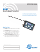
INSTRUCTION MANUAL SSM Micro Bodypack Transmitter This device has not been authorized as required by the rules of the Federal Communications Commission. This device is not, and may not be, offered for sale or lease, or sold or leased, until authorization is obtained. Quick Start Steps 1) Install a good battery and turn power on (see pages 5 and 9). 2) Set the compatibility mode to match the receiver (see page 8).
SSM 2 LECTROSONICS, INC.
Micro Body Pack Transmitter Table of Contents Introduction...............................................................................4 Three Block Tuning Range......................................................4 About Frequency Blocks.........................................................4 About Digital Hybrid Wireless®................................................4 Battery Charging......................................................................5 Battery Installation.......................
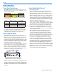
SSM Introduction Three Block Tuning Range About Digital Hybrid Wireless® The SSM transmitter tunes across a range of over 76 MHz. This tuning range covers three standard Lectrosonics frequency blocks. TUNING RANGE BLOCK BLOCK BLOCK Four tuning ranges are available covering standard blocks as follows: Range Blocks Covered Freq. MHz A1 470, 19, 20 470.1 - 537.5 B1 21, 22, 23 537.6 - 614.3 C1 24, 25, 26 614.4 - 691.1 D1* 27, 28, 29 691.2 - 767.
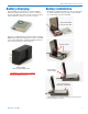
Micro Body Pack Transmitter Battery Charging The transmitter operates from a 3.7 V rechargeable battery that will provide about four hours of operation per charge. Battery life can be monitored from the timer function built into current Lectrosonics receivers. Battery Installation The battery compartment and door catch are designed for simple and quick battery changes, yet prevent the door from being opened accidentally.
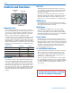
SSM Controls and Functions Modulation LEDs BATT LED BATT LED This LED glows green when the battery is good. The color changes to red when there is only a few minutes of operation left. The LED will blink briefly, just before the unit powers down. The exact point at which the LED turns red will vary with battery brand and condition, temperature and current drain. The LED is intended to simply catch your attention, not to be an exact indicator of remaining time.
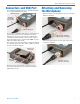
Micro Body Pack Transmitter Connectors and USB Port The housing is machined out of a solid aluminum billet for a rugged, lightweight assembly. Attaching and Removing the Microphone Align the ridges on the plug with the grooves in the jack and insert the plug. IR (infrared) port Galvanized steel flexible whip antenna Mic/Line input jack The antenna is a flexible whip made of galvanized steel, permanently attached to the transmitter to prevent damage from heavy use.
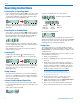
SSM Operating Instructions Powering On in Operating Mode Press and hold the Power Button for several seconds until a counter on the LCD progresses from 1 through 3, followed by a display of the model, firmware version, frequency block and compatibility mode. When you release the button, the unit will be operational with the RF output turned on and the Main Window displayed.
Micro Body Pack Transmitter Setup Screens DOWN Button Menu Hold the DOWN button while powering up the unit. Then press the AUDIO button repeatedly to scroll through the following settings. Use the UP and DOWN arrows to select the available options under each setting.
SSM Adjusting the Input Gain The two bicolor Modulation LEDs on the control panel provide a visual indication of the audio signal level entering the transmitter. The LEDs will glow either red or green to indicate modulation levels as shown in the following table.
Micro Body Pack Transmitter IR (infrared) Sync An IR (infrared) link between an associated receiver and the transmitter can be used to shorten setup time and ensure that the correct settings in the transmitter are made. The dome on the side panel of the transmitter is the port used for the IR link. The receiver is normally used to identify a clear operating frequency. Once step size, frequency and compatibility mode are set in the receiver, the settings can be sent to the transmitter via this IR link.
SSM Accessories Rechargeable battery P/N 40098 3.7V lithium-ion battery pack Battery charger P/N 40100 charger for Lectrosonics P/N 40098 lithiumion battery Replacement belt clip P/N 26995 slide-on belt clip for SSM transmitter 12 LECTROSONICS, INC.
Micro Body Pack Transmitter Specifications Operating Frequencies: Band A1: 470.100 - 537.575 Band B1: 537.600 - 614.375 Band C1: 614.400 - 691.175 Band D1: 691.200 - 767.975 (export only) Frequency Selection Steps: Selectable; 100 kHz or 25 kHz RF Power output: Selectable; 25 or 50 mW Pilot tone: 25 to 32 kHz; 5 kHz deviation (Digital Hybrid mode) Frequency Stability: ± 0.002% Deviation: ± 75 kHz max.
SSM Service and Repair If your system malfunctions, you should attempt to correct or isolate the trouble before concluding that the equipment needs repair. Make sure you have followed the setup procedure and operating instructions. Check the interconnecting cables. We strongly recommend that you do not try to repair the equipment yourself and do not have the local repair shop attempt anything other than the simplest repair.
Micro Body Pack Transmitter Rio Rancho, NM 15
LIMITED ONE YEAR WARRANTY The equipment is warranted for one year from date of purchase against defects in materials or workmanship provided it was purchased from an authorized dealer. This warranty does not cover equipment which has been abused or damaged by careless handling or shipping. This warranty does not apply to used or demonstrator equipment. Should any defect develop, Lectrosonics, Inc. will, at our option, repair or replace any defective parts without charge for either parts or labor.