
User's Manual


SSM
LECTROSONICS, INC.
10
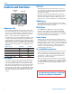
Input Jack Configuration
Looking into the 3 pin Lemo mic connector from the
outside of the transmitter, the pin centered in the two
guide slots is pin 1 and is ground. At 7 o’clock is pin 2
with a 2k resistor to ground. That 2k is a source load
for the Sanken COS-11 to save putting a resistor in the
connector. At 4 o’clock is pin 3, the servo audio input.
Pin 1 - ground
Pin 2 - 2k source load to ground
Pin 3 - servo input
Voltages, phase, impedance, and line level for all mics
signal sources are selected by menus. Pin 3 is the only
connection for all mics except for the aforementioned
Sanken COS-11. Countryman, DPA, Sanken COS-11
and standard two wire mics can be configured in the
menus. The Sanken CUB-01 is not supported.
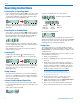
Locking the Controls
The keypad can be locked to prevent inadvertent
changes to be made to the transmitter. Press and hold
both the UP and DOWN arrow buttons for several
seconds until a countdown is completed on the LCD.
The display will show unloc 3...2...1 and then Loc will
appear. Remove the battery to unlock the controls.
Remote Control
Remote control signals (“dweedle tones”) may be used
to control the transmitter. The tones are played back into
the microphone to avoid the need to reach and handle
the transmitter when making changes to the following
adjustments and settings:
• InputGain
• Sleep/Unsleep
• Lock/Unlock
• Txpoweroutput
• Frequency
A smart phone app is available in the App Store and in
Google Play to implement this control. Search for the
title LectroRM.
Adjusting the Input Gain
The two bicolor Modulation LEDs on the control panel
provide a visual indication of the audio signal level
entering the transmitter. The LEDs will glow either red
or green to indicate modulation levels as shown in the
following table.
Signal Level -20 LED -10 LED
Less than -20 dB Off Off
-20 dB to -10 dB Green Off
-10 dB to +0 dB Green Green
+0 dB to +10 dB Red Green
Greater than +10 dB Red Red
NOTE: Full modulation is achieved at 0 dB, when
the “-20” LED first turns red. The limiter can cleanly
handle peaks up to 30 dB above this point.
It is best to go through the following procedure with the
transmitter in the standby mode so that no audio will en-
ter the sound system or recorder during adjustment.
1) With a charged battery in the transmitter, power the
unit on in the standby mode (see previous section
Powering On in Standby Mode).
2) Press and hold the AUDIO button with Aud and a
numeral on the display (e.g. Aud 22).
3) Prepare the signal source. Position a microphone
the way it will be used in actual operation and have
the user speak or sing at the loudest level that oc-
cur during use, or set the output level of the instru-
ment or audio device to the maximum level that will
be used.
4) Use the and arrow buttons to adjust the gain
until the –10 dB glows green and the –20 dB LED
starts to flicker red during the loudest peaks in the
audio.
5) Once the audio gain has been set, the signal can
be sent through the sound system for overall level
adjustments, monitor settings, etc.
6) If the audio output level of the receiver is too high or
low, use only the controls on the receiver to make
adjustments. Unless the microphone or its position
changes, or a different instrument is being used,
leave the transmitter gain adjustment set accord-
ing to these instructions. Use the audio output level
control on the receiver to make adjustments for
the desired level being delivered to the connected
mixer, recorder, etc.