
User's Manual


SSM
LECTROSONICS, INC.
6
Controls and Functions
Modulation LEDs
Proper input gain adjustment is critical to ensure the
best audio quality. Two bicolor LEDs will glow either red
or green to accurately indicate modulation levels. The
input circuitry includes a wide range DSP controlled
limiter to prevent distortion at high input levels.
It is important to set the gain (audio level) high enough
to achieve full modulation during louder peaks in the
audio. The limiter can handle over 30 dB of level above
full modulation, so with an optimum setting, the LEDs
will flash red during use. If the LEDs never flash red, the
gain is too low. In the table below, +0 dB indicates full
modulation.
Signal Level -20 LED -10 LED
Less than -20 dB Off Off
-20 dB to -10 dB Green Off
-10 dB to +0 dB Green Green
+0 dB to +10 dB Red Green
Greater than +10 db Red Red
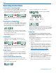
LCD Screen
The LCD is a numeric-type Liquid Crystal Display with
screens for adjusting output power, frequency, audio
level, low frequency audio roll-off and various modes
and options. The transmitter can be powered up with or
without the RF output turned on. A brief press on the
power button turns the unit on in a Standby Mode with
the output turned off to allow adjustments to be made
without interfering with other wireless systems in the
vicinity.
BATT LED
This LED glows green when the battery is good. The
color changes to red when there is only a few minutes
of operation left. The LED will blink briefly, just before
the unit powers down.
The exact point at which the LED turns red will vary
with battery brand and condition, temperature and cur-
rent drain. The LED is intended to simply catch your
attention, not to be an exact indicator of remaining time.
AUDIO Button
The AUDIO button is used to adjust the audio output
level and low frequency roll-off. Each press of the button
will toggle between the two settings.
FREQ Button
The FREQ Button displays the selected operating
frequency and toggles the LCD between displaying
the actual operating frequency in MHz and a two-digit
hexadecimal number that corresponds to the equivalent
Lectrosonics Frequency Switch Setting.
Power Button
Turns the unit on and off. A brief press turns power on
in a Standby Mode to make settings without interfering
with other wireless systems in the vicinity. Pressing and
holding the button until a counter on the LCD completes
a sequence turns the power on with the RF output
turned on. Pressing and holding for the duration of a
countdown turns the unit off.
UP and DOWN Arrow Buttons
The Up and Down arrow buttons are used to select the
values on the various setup screens and to lock out
the control panel. Press and hold both buttons until a
countdown is completed to lock the keypad. Remove
the battery to unlock the keypad.
These arrow keys also turn the LEDs on and off. With
no other button pressed, the UP arrow turns the LEDs
on and the DOWN arrow turns them off. When the LEDs
are tuned off, the LCD with display a reminder every
few seconds.
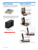
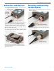
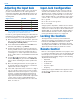
Power Button
Modulation
LEDs
BATT LED
See Operating Instructions and Setup
Screens for compete information.