UT195 HAND-HELD TRANSMITTER OPERATING INSTRUCTIONS and trouble-shooting guide LECTROSONICS, INC.
INTRODUCTION Thank you for selecting the Lectrosonics T195 hand-held wireless transmitter. The T195 combines over 80 years of engineering experience with the very latest compo nents in a design that addresses the most demanding professional applications. The design of the T195 was the direct result of numerous conversations with users, staging and touring companies and dealers across the US.
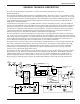
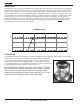
Hand-held Transmitter GENERAL TECHNICAL DESCRIPTION The T195 / UT195 transmitter is comprised of a number of functional sub-systems as shown in the block diagram below. The T195 and UT195 utilize 75kHz deviation for compatibility with the 195 series receivers. The transmitter circuits are all regulated to allow full output power from the beginning (9 Volts) to the end (7 Volts) of battery life. The oscilla tor crystal is shock mounted to provide ruggedness.
The 195 system utilizes a separate ultrasonic tone modulation of the basic carrier to operate the receiver squelch. A 32kHz tone is injected into the audio signal after the microphone preamp, just after the compandor. The supersonic pilot tone is filtered out of the audio signal immediately after the detector in the receiver so that it does not influence the compandor or various gain stages.
Hand-held Transmitter EXTERNAL SWITCHES BYPASS This concealed slide switch defeats the external switches on the bottom panel for applications where it is best that the user not be able to operate the power and mute switches. EXTERNAL LED OFF This slide switch defeats the battery status LED on the bottom panel for applications where the LED may be distracting. With this switch in the right-hand position, the power will remain on and the transmitter operating, even though the power LED is off.
BASS FILTER In addition to the tone controls, the UT200 also has a built in bass filter. This filter is fixed and cannot be adjusted or defeated. Low frequency noise is much more of a problem with wireless microphones than with conventional micro phones. With a regular mic, low frequency wind noise, breath thumps or handling rumble can be filtered out at the control board before the noise causes problems with the following electronics or speaker systems.
Hand-held Transmitter BATTERY INSTALLATION The transmitter is powered by a standard alkaline 9 Volt battery. It is important that you use ONLY an ALKALINE battery for reliable operation. Alkaline batteries will provide about 4 hours of operation and lithium batteries will power the unit for 12 hours. The battery status lamp will function normally only with alkaline batteries. Standard zinc-carbon batteries marked “heavy duty” or “long-lasting” are not adequate.
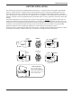
OPERATING INSTRUCTIONS 1) Install a fresh battery according to the instructions on page 5. Leave the battery cover off for further adjustment. 2) Set the internal bypass slide switches so that the battery status LED and the bottom panel switches will operate. 3) On the bottom panel, move the “A” (audio) switch to “OFF” and the “P” (power) switch to ON (in that order). Observe that the battery status LED is brightly lit. If the LED is dim, replace the battery.
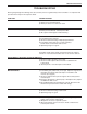
Hand-held Transmitter TROUBLESHOOTING Before going through the following chart, be sure that you have a good battery in the transmitter. It is important that you follow these steps in the sequence listed. SYMPTOM POSSIBLE CAUSE TRANSMITTER BATTERY LED OFF 1) External LED is turned off. Check internal slide switch. 2) Battery is inserted backwards. 3) Battery is dead, or too low to be used. NO TRANSMITTER MOD LEVEL LEDs 1) Gain control turned all the way down. 2) Battery is in backwards.
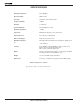
SPECIFICATIONS Operating Frequencies: 470 to 608 MHz RF Power Output: 50mW on VHF Pilot Tone: 32.768 kHz, ±2 Hz, 5kHz deviation Frequency Stability: ±0.
Hand-held Transmitter SERVICE AND REPAIR If your system malfunctions, you should attempt to correct or isolate the trouble before concluding that the equipment needs repair. Make sure you have followed the setup procedure and operating instructions.
LIMITEDONE ONE YEAR LIMITED YEARWARRANTY WARRANTY The equipment is warranted for one year from date of purchase against defects in materials or workmanship provided it was purchased from an authorized dealer. This warranty does not cover equipment which has been abused or damaged by careless handling or shipping. This warranty does not apply to used or demonstrator equipment. Should any defect develop, Lectrosonics, Inc.