UCR195 COMPACT UHF RECEIVER OPERATING INSTRUCTIONS and troubleshooting guide LECTROSONICS, INC.
Compact UHF Receiver Table of Contents INTRODUCTION TO THE 195 SYSTEM ................................................. 4 GENERAL TECHNICAL DESCRIPTION UCR195 RECEIVER ............................................................................ 6 FRONT PANEL CONTROLS AND FUNCTIONS .................................... 8 REAR PANEL CONTROLS AND FUNCTIONS ...................................... 9 ANTENNA USE AND PLACEMENT ...................................................... 10 OPERATING INSTRUCTIONS ........
INTRODUCTION TO THE 195 SYSTEM The 195 Series system was designed for the most critical studio and sound reinforcement applications. The system design represents a significant step forward in wireless microphone technology. Every stage in the entire audio/radio chain from transmitter input to re ceiver output was evaluated and analyzed to produce the operating parameters and performance requirements for this entirely new design.
Compact UHF Receiver NO PRE-EMPHASIS/DE-EMPHASIS The signal to noise ratio of the 195 system is high enough to preclude the need for conventional preemphasis (HF boost) in the transmitter and de-emphasis (HF roll off) in the receiver.
GENERAL TECHNICAL DESCRIPTION UCR195 RECEIVER The UCR195 is a high performance, dual-conversion, UHF receiver. The RF performance is extremely stable over a very wide temperature range, making the UCR195 perfectly suited to the rough environmental conditions found in the field. The proprietary audio processing includes a dual-band compandor for very low distortion and a superior signal to noise ratio.
Compact UHF Receiver The UCR195 detector basically works like this: A stream of DC pulses is generated at 455kHz. The pulse width is constant, but the timing between pulses varies with the frequency shift of the FM signal. The pulse stream is controlled by the FM signal coming from the IF section which has been heavily limited. The average voltage of the pulses within any given time interval varies in direct proportion to the frequency modulation of the radio signal, producing the audio signal.
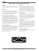
FRONT PANEL CONTROLS AND FUNCTIONS PWR LED When lit, this LED indicates that power is applied to the UCR195 and adequate voltage is present to operate the unit. MONITOR This is a high quality audio output to drive a wide variety of different types of headphones. It is also useable as a secondary audio output to feed recorders or external audio devices. The Monitor jack is a mini stereo type with the same signal applied to the tip and ring contacts.
Compact UHF Receiver REAR PANEL CONTROLS AND FUNCTIONS EXTERNAL POWER JACK The UCR195 can be powered from external 12 to 18 Volts DC applied directly to this jack, or conventional 110 VAC sources via the supplied CH12 adapter. The UCR195 is protected from reverse polarity conditions which prevents damage if a positive ground power source is applied. The center pin of this jack is POSITIVE.
ANTENNA USE AND PLACEMENT Position the antenna so that it is more than 3 or 4 feet from large metal surfaces. If this is not possible, try to position the antenna so that it is as far away from the metal surface as is practical. You can also let the metal surface work for you by aligning the antenna perpendicu lar to the surface. This will provide a ground plane for the antenna.
Compact UHF Receiver OPERATING INSTRUCTIONS 1. Connect the power cord or install the batteries. 2. Attach the antenna. 3. Connect the audio cable to the audio output XLR. 4. Set the front panel Audio Output Level control to minimum and set the Power switch to either Int or Ext, depend ing upon the power source. Check to see that the front panel Power LED lights up. 5. Adjust the transmitter gain. THIS IS PERHAPS THE MOST IMPORTANT STEP IN THE SET UP PROCE DURE.
TROUBLESHOOTING POWER SUPPLY AND FUSE LEDs not lit or dimly lit • AC power cord disconnected. • External power supply disconnected or inadequate. • Main power supply fuse tripped. Turn the receiver off, remove the cause of the overload and turn the receiver back on. • Wrong polarity power source. The external DC in requires POSITIVE to be on the center pin.
Compact UHF Receiver SERVICE AND REPAIR If your system malfunctions, you should attempt to correct or isolate the trouble before concluding that the equip ment needs repair. Make sure you have followed the setup procedure and operating instructions.
SPECIFICATIONS AND FEATURES Receiver Operating Frequencies: 470 to 608 MHz, crystal controlled Receiver Type: Dual conversion, superheterodyne Frequency Stability: ±0.002 % Front end selectivity: -22 dB at ±4 MHz IF Selectivity: >90 dB at ±300 kHz (10.7 IF) IF Frequency: 10.7 MHz (1st IF); 455 kHz (2nd IF) IF bandwidth: ±150 kHz at ½ power points Sensitivity 20 dB Sinad: 0.63 uV (-111 dBm), A weighted 60 dB Quieting: 1.
Compact UHF Receiver Rio Rancho, NM – USA 15
LIMITEDONE ONE YEAR LIMITED YEARWARRANTY WARRANTY The equipment is warranted for one year from date of purchase against defects in materials or workmanship provided it was purchased from an authorized dealer. This warranty does not cover equipment which has been abused or damaged by careless handling or shipping. This warranty does not apply to used or demonstrator equipment. Should any defect develop, Lectrosonics, Inc.