
Owner's manual


GENERAL TECHNICAL DESCRIPTION
UCR195 RECEIVER
The UCR195 is a high performance, dual-conversion,
UHF receiver. The RF performance is extremely stable
over a very wide temperature range, making the UCR195
perfectly suited to the rough environmental conditions
found in the field. The proprietary audio processing
includes a dual-band compandor for very low distortion
and a superior signal to noise ratio. The squelch system
is operated by a separate pilot tone and mutes the audio
output directly at the output connector. The audio output
is calibrated for exact level matching, with a ten LED bar
graph meter.
SIX-POLE HELICAL RESONATOR FRONT-END
The UCR195 utilizes a six-pole helical resonator for
front-end filtering. The helical resonators are custom
manufactured in-house to provide the high performance
needed, yet still fit into the small UCR195 package.
This outstanding front-end keeps the UCR195 from
being affected by high power, adjacent RF signals and
also provides extremely high image rejection.
GaAs FET FRONT-END FILTER COUPLING
The UCR195 utilizes an ultra low noise GaAs FET
amplifier in the front-end section to compensate for the
required losses between filter stages. The GaAs FET
devices are extremely quiet, especially at the higher
frequencies in the UHF band.
DOUBLE BALANCED DIODE MIXERS
A double balanced diode mixer is used in the UCR195 to
produce the 10.7 MHz IF signal. The mixer produces
output at only the sum and difference signals, with
minimal spurious signals. This mixer offers a very high
overload threshold and a high degree of isolation be-
tween ports. This translates to the ability of the receiver
to accept higher input signals without overloading and
causing distortion and less cross talk between receivers
in multiple system installations.
10 POLE LINEAR PHASE FILTER
The 1st IF amplifier is a 4 stage amp with 2 poles of
filtering after each stage. The filters are high quality,
low distortion, constant group delay ceramic filters. This
special type of filter is needed to accommodate the wide
deviation of the 195 system. The 2nd IF incorporates 2
more poles of filtering.
DIGITAL PULSE COUNTING DETECTOR
The UCR195 receiver uses an advanced digital pulse
counting detector to demodulate the FM signal, rather
than a conventional quadrature detector. The most
common problem with quadrature detectors is thermal
drift, particularly those that operate at higher frequencies
like 10.7 MHz. The UCR195 design presents an el-
egantly simple, yet highly effective solution to this age
old problem.
HELICAL
RESONATOR
GaAS
FET
470 - 608
MHz
XTAL
CONTROLLED
1ST
OSCILLATOR
8 POLE
LINEAR PHASE
FILTER
455KHZ
BP
FILTER
10.7MHz IF
AMP
2ND MIXER
&
IF AMP
COUNTING
DETECTOR
32 kHZ
BLOCKING
FILTER
HI-LEVEL
DIODE MIXER
XTAL
CONTROLLED
2ND
OSCILLATOR
2:1
EXPANDER
TREBLE
2:1
EXPANDER
BASS
AUDIO
AMP
MONITOR
OUT
OUTPUT LEVEL ADJUST
AND
RANGE SWITCH
XL
R
OU
T
PILOT
TONE
MUTE
HELICAL
RESONATOR
AMP
DISABLE
PILOT
TONE
MOD
AUDIO
LED BARGRAPH METER
AMP
PILOT
LED
AMP
ENABLE
REVERSE
POLARITY
PROTECTION
+9V
REGULATOR
PWR
LED
PWR ON
AND
LO BATT LOGIC
TURN ON/OFF
DELAY
CH12 IN
9V
BATTERIES
-8.8V
REGULATOR
V
CC
V
EE
INT
OFF
EXT
POWER
SWITCH
32kHZ
V+
MONITOR
LEVEL
3
2
1
METER
MODE
LO
HI
FIXED
HI
FIXED
LO
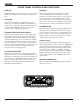
Figure 1 - UCR195 Block Diagram
6