UCR195D DIVERSITY UHF RECEIVER OPERATING INSTRUCTIONS and troubleshooting guide LECTROSONICS, INC.
Table of Contents INTRODUCTION TO THE 195 SYSTEM ................................................. 4 GENERAL TECHNICAL DESCRIPTION UCR195 RECEIVER ............................................................................ 6 FRONT PANEL CONTROLS AND FUNCTIONS .................................... 8 REAR PANEL CONTROLS AND FUNCTIONS ...................................... 9 ANTENNA USE AND PLACEMENT ...................................................... 10 OPERATING INSTRUCTIONS ..............................
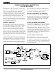
INTRODUCTION TO THE 195 SYSTEM The 195 Series system was designed for the most critical studio and sound reinforcement applications. The system design represents a significant step forward in wireless microphone technology. Every stage in the entire audio/radio chain from transmitter input to re ceiver output was evaluated and analyzed to produce the operating parameters and performance requirements for this entirely new design.
Diversity UHF Receiver NO PRE-EMPHASIS/DE-EMPHASIS The signal to noise ratio of the 195 system is high enough to preclude the need for conventional preemphasis (HF boost) in the transmitter and de-emphasis (HF roll off) in the receiver.
GENERAL TECHNICAL DESCRIPTION UCR195 RECEIVER The UCR195D is a high performance, dual-conversion, UHF receiver. The RF performance is extremely stable over a very wide temperature range, making the UCR195D perfectly suited to the rough environmental conditions found in the field. The proprietary audio processing includes a dual-band compandor for very low distortion and a superior signal to noise ratio.
Diversity UHF Receiver DIGITAL PULSE COUNTING DETECTOR The UCR195D receiver uses an advanced digital pulse counting detector to demodulate the FM signal, rather than a conventional quadrature detector. The most common problem with quadrature detectors is thermal drift, particularly those that operate at higher frequencies like 10.7 MHz. The UCR195D design presents an elegantly simple, yet highly effective solution to this age old problem.
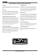
FRONT PANEL CONTROLS AND FUNCTIONS PWR LED When lit, this LED indicates that power is applied to the UCR195D and adequate voltage is present to operate the unit. PILOT LED The audio output muting (squelch) function of the UCR195D is controlled by a 32kHz tone modulation of the RF carrier. The audio output is muted until this tone is present. This LED will remain on as long as the receiver audio is enabled by the pilot tone.
Diversity UHF Receiver REAR PANEL CONTROLS AND FUNCTIONS EXTERNAL POWER JACK The UCR195D can be powered from external 12 to 18 Volts DC applied directly to this jack, or conventional 110 VAC sources via the supplied CH12 adapter. The UCR195D is protected from reverse polarity conditions which prevents damage if a positive ground power source is applied. The center pin of this jack is POSI TIVE.
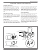
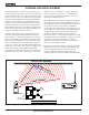
ANTENNA USE AND PLACEMENT Position the antennas so that they are more than 3 or 4 feet from large metal surfaces. If this is not possible, try to position them so they are as far away from the metal surface as is practical. You can also let the metal surface work for you by aligning the antenna perpendicular to the surface. This will provide a ground plane for the antenna.
Diversity UHF Receiver OPERATING INSTRUCTIONS 1. Connect the power cord or install the batteries. 2. Attach the antennas. 3. Connect the audio cable to the audio output XLR. 4. Set the front panel Audio Output Level control to minimum and set the Power switch to either Int or Ext, depend ing upon the power source. Check to see that the front panel Power LED lights up. 5. Adjust the transmitter gain. THIS IS PERHAPS THE MOST IMPORTANT STEP IN THE SET UP PROCE DURE.
TROUBLESHOOTING POWER SUPPLY AND FUSE LEDs not lit or dimly lit • AC power cord disconnected. • External power supply disconnected or inadequate. • Main power supply fuse tripped. Turn the receiver off, remove the cause of the overload and turn the receiver back on. • Wrong polarity power source. The external DC in requires POSITIVE to be on the center pin.
Diversity UHF Receiver SERVICE AND REPAIR If your system malfunctions, you should attempt to correct or isolate the trouble before concluding that the equip ment needs repair. Make sure you have followed the setup procedure and operating instructions.
SPECIFICATIONS AND FEATURES Receiver System Operating Frequencies: 470 to 608 MHz, crystal controlled (UCR195D receiver with UM195 transmitter) Receiver Type: Diversity reception, Dual conver sion, superheterodyne Audio Processor: Diversity Method: Phased antenna switching Frequency Stability: ±0.002 % Front end selectivity: -22 dB at ±4 MHz IF Selectivity: >90 dB at ±300 kHz (10.7 IF) Total Harmonic Distortion 1 kHz: 30 Hz to 20 kHz: Dual band compandor with no pre-emphasis/de-emphasis < 0.
Diversity UHF Receiver Rio Rancho, NM – USA 15
LIMITEDONE ONE YEAR LIMITED YEARWARRANTY WARRANTY The equipment is warranted for one year from date of purchase against defects in materials or workmanship provided it was purchased from an authorized dealer. This warranty does not cover equipment which has been abused or damaged by careless handling or shipping. This warranty does not apply to used or demonstrator equipment. Should any defect develop, Lectrosonics, Inc.