
Manual

GENERAL TECHNICAL DESCRIPTION
front end, it would be a shame to waste the performance with a
second rate mixer. In other designs that is exactly what happens
since mediocre mixers cause more intermodulation problems than
mediocre front ends. The only solution was a high power, double
balanced diode mixer driven by a local oscillator with more output
power than most wireless transmitters (50 mW). The mixer in the
UCR200D produces output at only the sum and difference signals,
with minimal spurious signals. This mixer offers a very high
overload threshold and a high degree of isolation between ports.
The IF output of this mixer is at 71 MHz which is unusually high
for a wireless receiver. This high frequency was chosen to increase
the image rejection in the front end to as high or a higher level than
our fixed frequency designs. The mixer is followed by high
current, low noise amplifiers and SAW filters to preserve the
superior RF performance.
SURFACE ACOUSTIC WAVE FILTER
The UCR200D is unique in that it uses state of the art SAW filters
in each IF section. The SAW filters are the only filter that can
combine sharp skirts, constant group delay, and wide bandwidth in
one filter. Though expensive, this special type of filter allows us to
follow the basic receiver rule of doing the primary filtering as early
as possible, at as high a frequency as possible and before high gain
is applied to the signal. Since these filters are made of quartz, they
are very temperature stable. Conventional LC filters at these
frequencies don’t begin to perform as well and in addition would
drift unacceptably in the elevated temperatures of an equipment
rack. After following the rule in a rigorous way, and due to the
sharp filtering action of the SAW filters, the 71MHz signal is
converted to the low frequency of 455 kHz. Lots of gain is then
applied in a conventional IC and the signal is then converted to
audio. 455 kHz is very unconventional for a second IF in a wide
deviation (±75 kHz) system. We chose to use 455 kHz to obtain an
outstanding AM rejection figure over a very wide range of signal
strengths and to produce an excellent noise improvement at low
signal strengths (capture ratio). To use an IF at 455 kHz requires
an unusual circuit to convert the IF to audio.
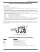
DIGITAL PULSE COUNTING DETECTOR
The UCR200D receiver uses an advanced digital pulse detector to
demodulate the FM signal, rather than a conventional quadrature
detector. The common problem with quadrature detectors is ther-
mal drift, particularly those that operate at higher frequencies like
10.7 MHz. Though the quadrature detectors may work well at
room temperature, if they are not carefully compensated, they will
produce amplitude changes and audio distortion in the elevated
temperatures of an equipment rack. Some manufacturers try to get
around the problem by tuning their systems at higher temperatures
after they’ve been on for some time. This just means that for the
first hours in a cool room the receiver is well out of specification or
after a few hours in a hot rack.
The UCR200D design presents an elegantly simple, yet highly
effective solution to this age old problem. The UCR200D detector
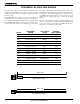
basically works like this: A stream of precision pulses is gener-
ated at 455KHz locked to the FM signal coming from the 455 kHz
IF section. The pulse width is constant, but the timing between
pulses varies with the frequency shift of the FM signal. The
integrated voltage of the pulses within any given time interval
varies in direct proportion to the frequency modulation of the radio
signal. Another way of describing it is that as the FM modulation
increases the frequency, the circuit produces more pulses and as
the modulation decreases the frequency, the circuit produces fewer
pulses. More pulses produces a higher voltage and fewer pulses a
lower voltage. The resultant varying voltage is the audio signal.
This type of detector eliminates the traditional problems with
quadrature detectors and provides very low audio distortion, high
temperature stability and stable audio level. The counting detector
also adds additional AM rejection, in addition to the limiting in the
IF section. The amplitude of the pulses is constant, so level
differences in the IF signal do not affect the pulse.
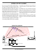
TRI MODE DYNAMIC FILTER
The audio signal is passed through a “dynamic noise reduction
circuit”. The cutoff frequency of this filter is varied automatically
by measuring the amplitude and frequency of the audio signal and
the quality of the RF signal. The audio bandwidth is held only to
that point necessary to pass the highest frequency audio signal
present at the time. If the RF level is weak, then the filter becomes
more aggressive. This results in a dramatic reduction of “hiss” at
all times. During passages with a high frequency content, this
filter gets completely “out of the way” and passes the signal with
no decrease in high-frequency response. Keep in mind that if hiss
is added to a signal, there is a psycho acoustic effect that makes
the sound seem brighter. The other side of this is that if hiss is
removed from a signal it will sound duller. Basically the ear’s
detection apparatus is pre-sensitized to high frequency sounds by
small amounts of high frequency hiss. Consider this effect when
making a judgment about the sound quality of various wireless
systems and this particular filter. We have satisfied ourselves
through elaborate tests that this filter is totally transparent.
PILOT TONE MUTE (SQUELCH)
The 200 system utilizes a separate ultrasonic tone modulation of
the basic carrier to operate the receiver squelch. In the transmitter,
a 32kHz tone is injected into the audio signal path just after the
compandor. The supersonic pilot tone is filtered out of the audio
signal immediately after the detector in the receiver so that it does
not influence the compandor or various gain stages.
The basic benefit of the pilot tone squelch system is that the
receiver will remain squelched (muted) until it receives the pilot
tone from the matching transmitter, even if a strong RF signal is
present on the carrier frequency of the system. Once a pilot tone is
received, the receiver will remain open during all signal condi-
tions.
The mute circuit drives a relay which physically disconnects the
output amplifier from the output. This provides complete muting
of the audio and the noise. The pilot tone function may be
bypassed with the Pilot Tone Disable switch (located on the front
panel.) When the pilot tone has been disabled with this switch, the
Pilot LED will glow red and the MOD function of the LED
bargraph meter on the front panel is disabled. The Pilot LED on
the front panel will glow green when the pilot tone has enabled the
receiver audio output.
4