
Manual
UHF Wireless Diversity Receiver
INSTALLATION AND OPERATING INSTRUCTIONS
1. Connect the power cord.
2. Attach the antennas.
3. Connect the audio cable to the audio output XLR.
4. Set the front panel Audio Output Level control to minimum and set the Power switch to ON (right position.) Check to see that the
front panel Power LED lights up.
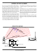
5. Adjust the transmitter gain. THIS IS PERHAPS THE MOST IMPORTANT STEP IN THE SET UP PROCEDURE. See your
transmitter manual (Operating Instructions section) for details on how to adjust the transmitter gain. In general, adjust the transmitter
gain so that the voice peaks will cause the 0dB LED on the front of the receiver to light on the loudest peak audio levels. This will
result in the best possible signal to noise ratio for the system without causing overload distortion.
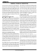
6. Adjust the Audio Output control according to the type of input on your equipment. The Range switch sets the adjustment range of the
front panel Audio Output control and has three positions.
Low: The adjustment range is from –50dBm to –20dBm.
Mid: Allows an adjustment from –30dBm to 0dBm
High: Sets the audio output to a fixed +8dBm with no front panel control.
The input levels of different cameras, VCRs, and PA equipment vary, which may require that you set the Audio Output control to an
intermediate position. Try different settings and listen to the results. If the output of the receiver is too high, you may hear distortion
or a loss of the natural dynamics of the audio signal. If the output is too low, you may hear steady noise (hiss) along with the audio.
The UCR200D audio output is designed to drive any audio input device from microphone level to +8dBm line level.
Note:
When using the +8 dBm HI position of the output range switch, do not ground pin 2 or pin 3 of the XLR output! The output impedance is
only 50 Ohms (unbalanced) when in the HI position and this is not enough to isolate the audio amplifier from a short to ground.
Distortion will result.
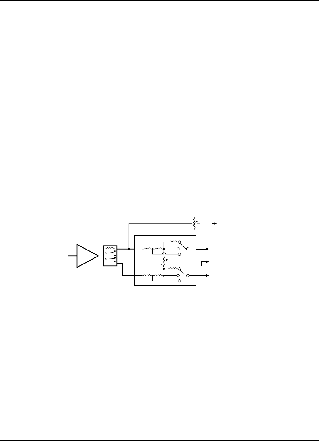
AMP
MONITOR
LEVEL
2 (Hi)
1 (Common or Ground)
LO
MID
HI
50
511
1k
50
511
511
511
MUTE
RELAY
LO
MID
HI
AUDIO
AMP
MONITOR
OUT
XLR
OUT
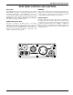
OUTPUT LEVEL ADJUST
AND RANGE SWITCH
3 (Lo)
UCR200D Simplified Audio Output Circuit
UCR200D REPLACEMENT PARTS and ACCESSORIES
Part No. Description
UHF Rubber Duck Antenna, straight connector
32251 Velcro mounting strips
35753 Zippered, padded vinyl system pouch
CH20 AC Power Adapter, 110V input, 12VDC output
PS200 Power supply cable locking plug on one end and a
Hirose plug on the other for hookup to a camera.
21586 Power supply cable with locking plug on one end and pigtail leads on the other
Rio Rancho, NM – USA
9