UCR300 DIVERSITY UHF RECEIVER OPERATING INSTRUCTIONS and trouble-shooting guide LECTROSONICS, INC. www.lectrosonics.
Table of Contents GENERAL TECHNICAL DESCRIPTION ........................................ 3 GENERAL TECHNICAL DESCRIPTION ........................................ 4 GENERAL TECHNICAL DESCRIPTION ........................................ 5 FRONT PANEL CONTROLS AND FUNCTIONS ........................... 6 REAR PANEL CONTROLS AND FUNCTIONS ............................. 7 ANTENNA USE AND PLACEMENT .............................................. 8 INSTALLATION AND OPERATING INSTRUCTIONS....................
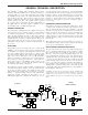
UHF Wireless Diversity Receiver GENERAL TECHNICAL DESCRIPTION The UCR300 is a portable, high performance, dual-conversion, frequency synthesized, UHF receiver. The RF performance is extremely stable over a very wide temperature range, making the UCR300 perfectly suited to the rough environmental condi tions found in the field. The proprietary audio processing includes a dual-band compandor for very low distortion and a superior signal to noise ratio.
GENERAL TECHNICAL DESCRIPTION DOUBLE BALANCED DIODE MIXERS In all wireless receivers, a mixer is used to convert the carrier frequency to the IF frequency where most of the filtering and gain in the receiver takes place. After doing all the right things in the front end, it would be a shame to waste the performance with a second rate mixer. In other designs that is exactly what happens since mediocre mixers cause more intermodulation problems than mediocre front ends.
UHF Wireless Diversity Receiver GENERAL TECHNICAL DESCRIPTION The mute circuit drives a relay which physically disconnects the output amplifier from the output. This provides complete muting of the audio and the noise. The pilot tone function may be bypassed with the Pilot Tone Disable switch (located on the front panel.) When the pilot tone has been disabled with this switch, the Pilot LED will glow red and the MOD function of the LED bargraph meter on the front panel is disabled.
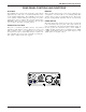
FRONT PANEL CONTROLS AND FUNCTIONS POWER LED When lit, this LED indicates that power is applied to the UCR300 and adequate voltage is present to operate the unit. PILOT LED The audio output muting (squelch) function of the UCR300 is controlled by a 32kHz tone modulation of the RF carrier. The audio output is muted until this tone is present. This green LED will remain on as long as the receiver audio is enabled by the pilot tone.
UHF Wireless Diversity Receiver REAR PANEL CONTROLS AND FUNCTIONS DC IN JACK MONITOR The UCR300 can be powered from external 10 to 16.5 Volts DC applied directly to this jack, or conventional 220 VAC sources via the supplied CH20 adapter. The UCR300 is protected from reverse polarity conditions which prevents damage if a positive ground power source is applied. The center pin of this jack is POSITIVE. This power connector is threaded to allow the plug to be locked in preventing accidental pull-out.
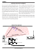
ANTENNA USE AND PLACEMENT There are two antenna assemblies included with this receiver. Position the antennas at least three or four feet apart and so that they are not within 3 or 4 feet of large metal surfaces. If this is not possible, try to position the antennas so that they are as far away from the metal surface as is practical. It is also good to position the receiver so that there is a direct “line of sight” between the transmitter and the receiver antenna.
UHF Wireless Diversity Receiver INSTALLATION AND OPERATING INSTRUCTIONS 1. Connect the power cord. 2. Attach the antennas. 3. Connect the audio cable to the audio output XLR. 4. Set the front panel Audio Output Level control to minimum and set the Power switch to ON (right position.) Check to see that the front panel Power LED lights up. 5. Adjust the transmitter gain. THIS IS PERHAPS THE MOST IMPORTANT STEP IN THE SET UP PROCEDURE.
FREQUENCY BLOCKS AND RANGES The table below lists the factory designated frequency ranges available for the UCR300 receiver. For convenience, the table includes information about the UM300B belt-pack transmitter antennas as well. Each UCR300 receiver is built to cover a pre-selected range of frequencies (a “block”) as shown below. The receiver will tune to any of 256 different frequencies within this factory assigned block.
UHF Wireless Diversity Receiver TROUBLESHOOTING POWER SUPPLY AND FUSE AUDIO SIGNAL QUALITY LEDs not lit or dimly lit Poor signal to noise ratio • External power supply disconnected or inadequate. • Transmitter gain set too low • Main power supply fuse tripped. Turn the receiver off, remove the cause of the overload and turn the receiver back on. • Noise may not be in wireless system. Mute the audio signal at the transmitter and see if noise remains.
SPECIFICATIONS AND FEATURES Operating Frequencies: Frequency Adjustment Range: Receiver Type: Frequency Stability: Front end selectivity: Sensitivity 20 dB Sinad: 60 dB Quieting: Squelch quieting: AM rejection: Modulation acceptance: Image and spurious rejection: Third order intercept: Diversity method: FM Detector: Antenna inputs: Audio outputs Rear Panel XLR: 537.600 to 862.000 MHz 25.5 MHz max Dual conversion, superheterodyne, 71MHz and 455kHz ±0.002 % >22 dB at ±4 MHz 0.
UHF Wireless Diversity Receiver This product meets the CE Compliance Standards - ETS 300 445; January 1996. A copy of the Declaration of Conformity may be requested from your dealer or by contacting the factory directly: Lectrosonics, Inc. Marketing Department 581 Laser Rd. NE, Rio Rancho, NM 87124 USA tel: 505-892-4501 fax: 505-892-6243 e-mail: marketing@lectrosonics.
LIMITED ONE ONE YEAR WARRANTY LIMITED YEAR WARRANTY The equipment is warranted for one year from date of purchase against defects in materials or workmanship provided it was purchased from an authorized dealer. This warranty does not cover equipment which has been abused or damaged by careless handling or shipping. This warranty does not apply to used or demonstrator equipment. Should any defect develop, Lectrosonics, Inc.