Wireless Diversity Receiver UDR200A RA TIO DIVERSITY RECEIVER RATIO OPERA TING INSTR UCTIONS OPERATING INSTRUCTIONS and trouble-shooting guide LECTROSONICS, INC.
A little bit of Lectrosonics history... Founded in 1971, Lectrosonics began with the manufacture of portable sound systems sold under the Voice Projector© registered trademark. The first product line consisted of a self-contained lectern/sound system and two over-the-shoulder portable sound systems. In 1975 the first wireless microphone systems were introduced to audio visual markets. The first system was a lavalier system consisting of a beltpack transmitter and matching receiver.
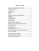
Wireless Diversity Receiver Table of Contents FRONT PANEL CONTROLS AND FUNCTIONS ............................ 4 TRANSMITTER AUDIO LEVEL .............................................................................. 4 RF LEVEL INDICATORS ........................................................................................ 4 OPTI-BLEND LEDs ................................................................................................. 4 PILOT LED .........................................................
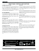
FRONT PANEL CONTROLS AND FUNCTIONS TRANSMITTER AUDIO LEVEL PILOT LED The modulation (audio level) of the incoming signal is indicated by a fast responding LED strip. The strip is calibrated in 6dB steps over an expanded scale (54dB) which provides an ex tremely accurate visual “picture” of the signal dynamics, even at a distance away from the receiver. Audio signal peaks easily exceed the response time of VU meters, however, the LED strip is fast enough to track even brief transients.
Wireless Diversity Receiver REAR PANEL CONTROLS AND FUNCTIONS AUDIO OUTPUT DC IN A calibrated control on the rear panel adjusts the output level in 5 dB steps, referenced in dBu. This control knob adjusts the absolute output level at the XLR connector. The AUDIO OUT PUT level control is located after the output transformer. This allows the signal to noise ratio to remain constant regardless of the setting of the control.
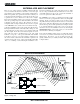
ANTENNA USE AND PLACEMENT There are two remote antenna assemblies included with this receiver. Position the antennas at least three or four feet apart and so that they are not within 3 or 4 feet of large metal surfaces. If this is not possible, try to position the antennas so that they are as far away from the metal surface as is practical. It is also good to position the receiver so that there is a direct “line of sight” between the transmitter and the receiver antenna.
Wireless Diversity Receiver INSTALLATION AND OPERATING INSTRUCTIONS 1) If operating the unit from AC power, determine the line voltage to be used and set the Line Voltage Selector on the rear panel to match. The units are shipped with the proper size fuse for use with 120V systems (315mA). If the unit will be used in a 220V environment, change the fuse to a 160mA of the same type.
TROUBLESHOOTING POWER SUPPLY AND FUSE ANTENNAS AND RF SIGNAL STRENGTH LEDs not lit or dimly lit — When the UDR200 is powered from an external DC supply, the LEDs are dimmed to conserve battery life. RF LEVEL is weak on one (or both) channels • AC power cord disconnected. • External power supply disconnected or inadequate. • Main power supply fuse blown. • For 110 Volt operation: 315 mA, 250 Volt Buss GDC-315 or Littlefuse 218.
Wireless Diversity Receiver UDR200 REPLACEMENT PARTS and ACCESSORIES Part No. Description A-185-BNC Telescoping 1/4 wave VHF/UHF whip; BNC connector. A-200 Remote dipole UHF/VHF antenna with aluminum mounting block; supplied with one built-in telescoping whip and one detachable telescoping whip. Operates on VHF or UHF frequencies. A-9775 Coaxial extension cable for A-200 dipole antenna; BNC male/ male connectors, 10 ft, RG-58 cable.
SERVICE AND REPAIR If your system malfunctions, you should attempt to correct or isolate the trouble before concluding that the equipment needs repair. Make sure you have followed the setup procedure and operating instructions. Check out the inter-connecting cords and then go through the TROUBLE SHOOTING section in the manual We strongly recommend that you do not try to repair the equipment yourself and do not have the local repair shop attempt anything other than the simplest repair.
Wireless Diversity Receiver SPECIFICATIONS AND FEATURES Operating Frequencies: Frequency Adjustment Range: Receiver Type: Frequency Stability: Front end selectivity: Sensitivity 20 dB Sinad: 60 dB Quieting: Squelch quieting: AM rejection: Modulation acceptance: Image and spurious rejection: Third order intercept: Diversity technique: FM Detector: Antenna inputs: Audio outputs Rear Panel XLR: Monitor out: Front Panel Controls and Indicators: Rear Panel Controls and features: Power Options: Weight: Dimens
LIMITED ONE YEAR WARRANTY The equipment is warranted for one year from date of purchase against defects in materials or workmanship provided it was purchased from an authorized dealer. This warranty does not cover equipment which has been abused or damaged by careless handling or shipping. This warranty does not apply to used or demonstrator equipment. Should any defect develop, we will, at our option, repair or replace any defective parts without charge for either parts or labor.