
Manual
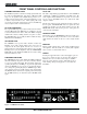
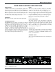

FRONT PANEL CONTROLS AND FUNCTIONS
TRANSMITTER AUDIO LEVEL
The modulation (audio level) of the incoming signal is indicated
by a fast responding LED strip. The strip is calibrated in 6dB
steps over an expanded scale (54dB) which provides an ex-
tremely accurate visual “picture” of the signal dynamics, even at
a distance away from the receiver. Audio signal peaks easily
exceed the response time of VU meters, however, the LED strip
is fast enough to track even brief transients.
RF LEVEL INDICATORS
Two separate LED strips are provided to indicate the level of the
incoming RF signals. The LED strips are calibrated to provide
accurate indications from 1uV to 1mV. The LEDs are highly
visible from a distance, making antenna set up more accurate.
The dual LED strips are especially useful in “trouble-shooting”
difficult antenna installations.
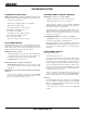
OPTI-BLEND LEDs
The UDR200 receiver operates with a method of audio ratio
blending of two audio outputs. RF level in each receiver is
compared and the audio signals from the two receivers are
mixed together in a ratio that favors the quieter receiver. As this
blending action occurs, the brightness of the two OPTI-BLEND
LEDs will vary. The brighter the LED, the more audio is being
mixed in from that receiver.
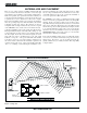
FREQUENCY SWITCHES
The UDR200 is frequency agile within the 5 MHz passband of
the front-end filters. To gain access to these switches, slide the
access door up with a fingernail. The left switch changes the
operating frequency by 1.6 MHz per step and the right switch
changes it 100 kHz per step. If you are experiencing interfer-
ence, change the operating frequency in 100 kHz steps to find a
clear channel. If it is not possible to find a clear channel using
the 100 kHz switch, return it to its original position and change
the 1.6 MHz switch by one click then try the 100 kHz switch
again.
PILOT LED
The audio output muting (squelch) function of the UDR200 is
controlled by a 33kHz tone modulation of the RF carrier. The
audio output is muted until this tone is present. As soon as the
tone is received, this LED is turned on to indicate the audio
output is enabled.
The pilot tone function can be defeated by pressing a switch on
the rear panel. The PILOT LED, however, operates the same
regardless of whether or not the defeat switch is pressed. The
PILOT LED strictly indicates the presence of the pilot tone
carrier from the transmitter.
DIVERSITY MODE
This switch is set to the DIVERSITY position for normal opera-
tion. For trouble-shooting or when the receiver is used with a
single antenna, the switch can be set to select a single antenna
only.
MONITOR
This is an audio output to drive a wide variety of different types
of headphones. It is also useable as a secondary audio output to
drive recorders or external audio devices.
POWER
Pressing the upper half of the rocker switch applies power to
the receiver. At turn on, there are various relays and delays
built into the receiver to allow various stages to stabilize
before the audio output is activated. This will prevent an
audio “thump” when powering up the receiver and/or the
transmitter.
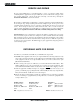
500
250
100
50
25
10
5
1uV
2uV 1mV
RF LEVEL
PILOT
OPTI
BLEND
A
B
MODE
LIM0-6-12
-18-24-30
-36
-42
-48
TX AUDIO LEVEL dB
POWER
A B
DIVERSITY
MONITOR
LECTROSONICS
FREQUENCY
1.6M
100K
Figure 1 - UDR200 Front Panel
4