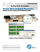
INSTALLATION GUIDE For firmware Ver. 4.0 and higher Venue Narrowband Receiver Modular Receiver System with 50 MHz Bandwidth Hardware/Software Installation and Configuration Fill in for your records: Serial Number: Purchase Date: Rio Rancho, NM, USA www.lectrosonics.
Venue Narrowband Receiver 2 LECTROSONICS, INC.
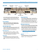
Digital Hybrid Wireless™ Modular Receiver System Introduction The Venue is a modular rack mount receiver for use with a wide variety of transmitters from Lectrosonics and other manufacturers. Designed for maximum versa tility and performance, the Venue receiver offers unprec edented flexibility for reliable operation, even in today’s increasingly congested RF environments. A Venue receiver is a “system” that consists of a master unit and up to six receiver modules.
Venue Narrowband Receiver 4 LECTROSONICS, INC.
Digital Hybrid Wireless™ Modular Receiver System Table of Contents Venue System Controls and Functions................................. 6 Front Panel............................................................................. 6 Rear Panel ............................................................................. 7 Hardware Installation .............................................................. 8 Receiver Modules .................................................................. 8 Rack Installation.
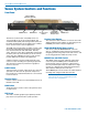
Venue Narrowband Receiver Venue System Controls and Functions Front Panel Function Button (labeled by the LCD) POWER Switch BACK Button Receiver Select Buttons PUSH FOR MENU/SELECT Rotary Control Headphone LEVEL Control PHONES Jack The Venue receiver master unit (VRM) serves as a “host assembly” for up to six receiver modules. The standard module (VRS) and tracking module (VRT) can be mixed and matched in the assembly in any combina tion to suit the needs of various applications.
Digital Hybrid Wireless™ Modular Receiver System Rear Panel Balanced Audio Outputs 4-6 Receiver Modules 4-6 Power Input RS-232 Port USB Port Multicoupler Outputs The rear panel provides six balanced XLR audio out puts, antenna inputs, “loop thru” antenna outputs from an internal multicoupler, a power jack with a locking connector, plus USB and RS-232 serial ports for setup and control. Receiver Modules Up to six receiver modules can be installed in each Venue receiver rack mount chassis.
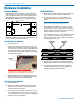
Venue Narrowband Receiver Hardware Installation Receiver Modules Rack Installation VRS and VRT receiver modules can be mixed in the same chassis, For ratio diversity operation, both mod ules in the pair must be on the same frequency block and positioned in the assembly in keeping with the OPTI-BLEND labeling on top of the chassis housing. Front panel 1. Mount the receiver(s) in the desired rack location(s). There are no special ventilation requirements. 2.
Digital Hybrid Wireless™ Modular Receiver System Audio Outputs Connections for Computer Interface Balanced XLR audio outputs on the rear panel can be used to drive balanced or unbalanced inputs at line level on any type of mixer, recorder or other type of audio equipment. Connection to a computer can be made via USB or RS-232 ports. Multiple units are easily connected using a USB hub. NOTE: Audio is not passed through these ports. They are used only for control and monitoring.
Venue Narrowband Receiver Powering On and Off When the Venue receiver is first powered up the LCD will show the firmware revision and the tuning range of the host assembly for a few seconds as the boot sequence begins. The receiver modules are then detected, which takes a few seconds. To turn the power off, press and hold the red power switch for several seconds. The LCD will display a mes sage briefly then power down.
Digital Hybrid Wireless™ Modular Receiver System Pressing the Receiver Select Button again will switch to the receiver module information screen to show the basic setup. Function Button Press the BACK button twice to return to the overview screen. From the overview screen, press the MENU/SELECT control to open the TopMenu, rotate the control to select an item, then press the control to enter the setup screen for that item.
Venue Narrowband Receiver System Setup with the LCD It is generally best to complete these steps in the se quence shown.
Digital Hybrid Wireless™ Modular Receiver System Three diversity reception modes are available: • Switched Diversity uses one receiver module per audio channel. • Ratio Diversity (OptiBlendTM) uses two receiver modules per audio channel. • Frequency Diversity uses two receiver modules and two transmitters per audio channel. Press the Receiver Select Buttons to enter the setup screens for the receiver modules.
Venue Narrowband Receiver Depending on how microphones are wired and other vagaries, either position of the INVT toggle switch might achieve the null. Keep toggling the switch until the null is found, adjust the level for the deepest null, then press INVT one more time to put the transmitter audio back in phase. 3. Repeat Steps 1 and 2 for each receiver module pair set to Frequency Diversity Mode.
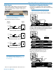
Digital Hybrid Wireless™ Modular Receiver System Finding Clear Channels with Tuning Groups The scanning begins automatically. Allow the scan ner to continue sweeping through the tuning range several times, then press the Function button to enter “Stop Mode.” Tuning Groups include two groups (“u” and “v”) that can be customized for specific applications and four precoordinated frequency groups (“a” through “d”) that are free from intermodulation. Groups “u” and “v” are blank by default.
Venue Narrowband Receiver Adjusting Audio Output Levels The audio output levels at the rear panel XLR jacks are software controlled. (The front panel LEVEL knob af fects the PHONES output only.) The optimum output level will provide the highest level signal possible without overloading the input to external equipment or driving a subsequent stage in the signal chain into limiting or compression.
Digital Hybrid Wireless™ Modular Receiver System Selected Receiver 3. When either the AA TIM or 9V TIM (timer) mode is selected, press the Function Button to reset (“ZERO”) the timer. Press the Function Button to Reset (ZERO) the Timer Battery Types for Each Receiver Module Current Transmitter Battery Voltage (when available) 2. Select each receiver module with the Receiver Select Button and set the battery type being used in the corresponding transmitter. 9V ALK Transmitter uses a 9V alkaline battery.
Venue Narrowband Receiver Installing LecNet2™ Software and USB Driver LecNet2 software includes VRpanel for easy setup and monitoring of the Venue Receiver using a computer system running Windows® 2000, XP or VistaTM operating systems. 2. On the first page of the Wizard, select Install from a list or specific location (Advanced) and click “Next>” to continue. Installing LecNet2™ Software 1. Remove any previously installed versions of Lec Net2™ software to make sure you are using the latest release. 2.
Digital Hybrid Wireless™ Modular Receiver System 5. When the driver installation is complete, the final page of the Wizard appears. Click “Finish” to close the Found New Hardware Wizard. USB Driver Installation (Windows XP) Subsequent Installations 3. When the driver installation is complete, the final page of the Wizard appears. Click “Finish” to close the Found New Hardware Wizard.
Venue Narrowband Receiver USB Driver Installation (Windows 2000) First Time Use the following procedure when a LecNet2™ device is connected to the Windows 2000-based PC for the first time. 4. When the driver is found, the LecNet2™ device name will be displayed along with the location of the driver. Click “Next >” to install the driver. 1. Connect a USB cable between the Venue Receiv er’s USB port and the USB port on the computer system.
Digital Hybrid Wireless™ Modular Receiver System Setting Up the Venue Receiver Using VRpanel Once the LecNet2™ software and USB drivers have been installed, the Venue receiver can be configured with a software interface and a computer using a Win dows® 2000, XP or VistaTM operating system. VRpanel is an intuitive software package that simplifies the setup and operation of the Venue receiver. This sec tion of this manual is limited to the basic setup and con figuration.
Venue Narrowband Receiver Main Window Top Menu Items The Main Window is organized in a straightforward manner with three pull down menus. Brief descriptions of these menus are presented here as an introduction. Full descriptions and instructions for the menu items are presented in the online Help. Popup Menu Items Right clicking anywhere in a receiver pane invokes a context-sensitive and position-sensitive popup menu.
Digital Hybrid Wireless™ Modular Receiver System Separate windows are presented for each frequency block. The scan results are presented in a graphical display with shaded areas indicating frequency and strength of RF signals. A scale in the middle of the display indicates the approximate signal strength in microvolts. Scanning continues until it is suspended by the user. Click Stop to suspend the scanning.
Venue Narrowband Receiver 24 LECTROSONICS, INC.
Digital Hybrid Wireless™ Modular Receiver System Antenna Use and Placement The Venue System is designed for rack mounting. Although it can be operated with two whip antennas, it is best to use remote antennas such as the SNA600 or ALP Series for optimum reception. Position the remote antennas at least three or four feet apart and not within three or four feet of large metal surfaces. If this is not possible, try to position the antennas so that they are as far away from the metal surface as is practical.
Venue Narrowband Receiver Pre-coordinated Frequencies Interference from IM (intermodulation) is a potential problem in all multi-channel wireless systems, so proper frequency coordination is always required to avoid noise, range and dropout problems.
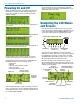
Digital Hybrid Wireless™ Modular Receiver System Compatibility Diagram BLOCK 24 Compatibility follows the pattern illustrated in the dia gram at right. Grp a and Grp b contain the 16 frequencies shown in the table below (upper orange/white set). All 16 within the same block are compatible Grp c and Grp d contain the 16 frequencies shown in the table below (lower blue/white set). NOTE: There is no assurance that frequencies are compatible between the upper orange/white set and the lower blue/white set.
Venue Narrowband Receiver Diagnostics Multi-channel System Checkout Interference can result from a wide variety of sources including TV station signals, other wireless equipment in use nearby, or from intermodulation within a multi channel wireless system itself. Regardless of how the frequencies were coordinated, a final checkout proce dure is always a good idea.
Digital Hybrid Wireless™ Modular Receiver System Accessories and Common Replacement Parts Remote Antennas ALP Series LPDA (log periodic dipole array) models SNA600 folding dipole antenna ALP500 ALP Kit mounting hardware ALP620 ALP650 Coaxial Cable ARG2 coaxial cable - 2 ft. length ARG15 coaxial cable - 15 ft. length ARG25 coaxial cable - 25 ft. length ARG50 coaxial cable - 50 ft. length ARG100 coaxial cable - 100 ft.
Venue Narrowband Receiver Service and Repair If your system malfunctions, you should attempt to correct or isolate the trouble before concluding that the equipment needs repair. Make sure you have followed the setup procedure and operating instructions. Check the interconnecting cables and then go through the TROUBLESHOOTING section in this manual.
Digital Hybrid Wireless™ Modular Receiver System Rio Rancho, NM, USA 31
LIMITED ONE YEAR WARRANTY The equipment is warranted for one year from date of purchase against defects in materials or workmanship provided it was purchased from an authorized dealer. This warranty does not cover equipment which has been abused or damaged by careless handling or shipping. This warranty does not apply to used or demonstrator equipment. Should any defect develop, Lectrosonics, Inc. will, at our option, repair or replace any defective parts without charge for either parts or labor.