
User Manual


12
Chapter 2. System Configuration
2–1
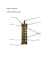
Transmitter Unit
Figure A. Transmitter block diagram
The transmitter unit consists of an Encoder Circuit and a Transmitter RF Circuit.
When the user presses a pushbutton on the transmitter, the Encoder Circuit senses
the pushbutton’s data immediately. The Encoder Circuit then encodes the
pushbutton’s data, combined with the ID Code and a Hamming Code to become the
"control data".
This control data goes to the transmitter RF circuit to modulate a radio frequency
(RF) carrier. The output FM signal from the modulator is then sent to the antenna
to generate the transmission signal via an RF amplifier and a low-pass filter.
2–2 Receiver Unit
Figure B. Receiver block diagram
The receiver unit consists of the Receiver/Decoder module and the Relay module.
RF signals (control data) from the transmitter are received by the antennas and sent
Encoder
Circuit
Transmitter
RF Circuit
Pushbuttons
Data
Antenna
Control Data
Relay contact outputs
(Connects to cranes
or other mechanical
devices)
ANT
Control data
Receiver/
Decoder
Module
Relay
Module
Cable
Command