User’s Manual 17529X.00 Series Models: 175290.00 175291.00 175292.
The LEESON 17529X.00 Series drives are chassis drives that accept a DC input voltage and output a DC power voltage to control the speed of a low voltage motor. The speed may be controlled with a potentiometer or an external voltage signal. Standard Features: • Provides smooth variable capability for mobile equipment. • Maintains variable speed control as batteries discharge. • Adjustable min speed, max speed, IR compensation, current limit, and accel.
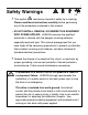
i Safety Warnings • This symbol denotes an important safety tip or warning. SHOCK HAZARD AVOID HEAT KEE DR OID ATION Please read these instructions carefully before performing any of the procedures contained in this manual. • DO NOT INSTALL, REMOVE, OR REWIRE THIS EQUIPMENT WITH POWER APPLIED. LEESON assumes the qualified technician is intimate with the dangers involving batteries, especially lead-acid type.
ii Contents Safety Warnings i Specifications 1 Dimensions 2 Installation 4 Mounting . . . . . . . . . . . . . . . . . . . . . . . . . . . . . . . . . . . . . . . . . . .4 Wiring . . . . . . . . . . . . . . . . . . . . . . . . . . . . . . . . . . . . . . . . . . . . .5 Heat sinking . . . . . . . . . . . . . . . . . . . . . . . . . . . . . . . . . . . . . . . .7 Fuse / Circuit breaker protection . . . . . . . . . . . . . . . . . . . . . . . . .7 Jumper 501 (JP501) . . . . . . . . . . . . . . . . . . .
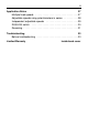
iii Application Notes 27 Multiple fixed speeds . . . . . . . . . . . . . . . . . . . . . . . . . . . . . . . .27 Adjustable speeds using potentiometers in series . . . . . . . . . . .28 Independent adjustable speeds . . . . . . . . . . . . . . . . . . . . . . . .29 RUN/JOG switch . . . . . . . . . . . . . . . . . . . . . . . . . . . . . . . . . . .30 Reversing . . . . . . . . . . . . . . . . . . . . . . . . . . . . . . . . . . . . . . . . .31 Troubleshooting 33 Before troubleshooting . . . . . . . . . . . .
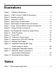
iv Illustrations Figure Figure Figure Figure Figure Figure Figure Figure Figure Figure Figure Figure Figure Figure Figure 1. 175290.00 Dimensions . . . . . . . . . . . . . . . . . . . . . . . . . . . .2 2. 175291.00 and 175292.00 Dimensions . . . . . . . . . . . . . . . .3 3. Heatsink mounting . . . . . . . . . . . . . . . . . . . . . . . . . . . . . . . .7 4. Jumper 501 (JP501) . . . . . . . . . . . . . . . . . . . . . . . . . . . . . .8 5. Speed Adjust Potentiometer . . . . . . . . . . . . . . . . . . .
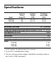
1 Specifications Model 175290.00 175291.00 175292.00 Max. Armature Current (Amps DC) 16 1 60 60 Max. Armature Voltage3 (VDC) 12 or 24 2 12 or 24 2 36 or 48 2 DC Voltage Input Range (VDC) 10–32 10–32 32–50 Acceleration Time Range 0.5 – 10 seconds Deceleration Time 0.5 seconds Analog Input Voltage Range (signal must be isolated; S1 to S2) 0 – 10 VDC Input Impedance (S1 to S2) 200KΩ Speed Regulation (% of base speed) 1% Speed Range 80:1 Form Factor 1.
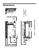
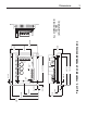
C506 6 IL501 POWER L501 C501 R502 2 C505 ALL DIMENSIONS IN INCHES [MILLIMETERS] 3.70 [94] 0.70 [18] Figure 1. 175290.00 Dimensions 6.90 [175] 5.50 [140] 6.30 [160] 0.50 [13] T JP501 1 2 3 Q502 0.30 [8] S3 S2 S1 C504 Q504 0.19 [5] 0.70 [18] 0.95 [24] 2.20 [56] 0.36 [9] 2.41 [61] 3.74 [95] 4.
Q504 JP501 1 2 3 C502 Q502 7.78 [198] 6.87 [174] 6.30 [160] MAX SPD IR COMP CUR LIMIT C507 Q501 0.88 [22] SO501 MIN SPD ACCEL C504 Q503 IL501 POWER C501 R502 R501 1 C505 1.96 [50] 6.30 [160] 3.00 [76] 1.99 [51] Figure 2. 175291.00 and 175292.00 Dimensions 0.15 [4] 1.01 [26] 3.21 [82] 0.74 [19] 0.49 [12] 3.60 [91] 6.38 [162] 6.90 [175] 0.
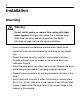
4 Installation Mounting Warning Do not install, rewire, or remove this control with input power applied. Doing so may cause fire or serious injury. Make sure you have read and understood the Safety Warnings on page i before attempting installation. • Drive components are sensitive to electrostatic fields. Avoid contact with the circuit board directly. Hold drive by the chassis only. • Protect the drive from dirt, moisture, and accidental contact.
Installation Wiring Warning Do not install, remove, or rewire this equipment with power applied. Failure to heed this warning may result in fire, explosion, or serious injury. This drive is isolated from earth ground. To prevent the risk of injury or fatality, avoid direct contact with the printed circuit board or with circuit elements. Do not disconnect any of the motor leads from the drive unless power is removed. Opening any one motor lead may destroy the drive.
6 Installation Shielding guidelines Warning Under no circumstances should power and logic leads be bundled together. Induced voltage can cause unpredictable behavior in any electronic device, including motor controls. As a general rule, LEESON recommends shielding of all conductors. If it is not practical to shield power conductors, LEESON recommends shielding all logic-level leads.
Installation 7 Heat sinking 175291.00 and 175292.00 drives are pre-mounted on a heat sink. For optimum heat transfer, mount the drive with heatsink fins standing vertically as shown in Figure 3 below. Heatsink Fins Figure 3. Heatsink mounting Fuse / Circuit breaker protection All LEESON drives should be protected by a fuse or circuit breaker. Use a fast acting fuse or circuit breaker rated for approximately 200% of the maximum armature current and armature voltage.
8 Installation Jumper 501 (JP501) LEESON 17529X.00 series drives are shipped with JP501 open (no jumper applied). This allows you to use 24 VDC motors with the 175290.00 and 175291.00, or 48 VDC motors with the 175292.00. To use lower voltage DC motors (12 VDC or 36 VDC, respectively) jumper pins 2 and 3 with the jumper provided. See Figure 4 for the location of JP501. 175290.00 = 16 Amp 12/24 VDC 175291.00 = 60 Amp 12/24 VDC 175292.
Installation Speed adjust potentiometer Warning Be sure that the potentiometer tabs do not make contact with the potentiometer enclosure. Grounding the input will cause damage to the drive. Mount the speed adjust potentiometer through a 0.38 in. (10 mm) hole with the hardware provided (see Figure 5 on Page 10). Install the circular insulating disk between the panel and the 10K ohm speed adjust potentiometer. Twist the speed adjust potentiometer wire to avoid picking up unwanted electrical noise.
10 Installation MOUNT THROUGH A 0.38 IN. (10 MM) HOLE WIPER CW W NUT STAR WASHER SPEED ADJUST POTENTIOMETER INSULATING DISK PANEL Figure 5. Speed Adjust Potentiometer C507 C502 C504 S1 10K OHM SPEED POTENTIOMETER 1 2 3 JP501 S2 S3 SO501 MIN SPD ACCEL MAX SPD IR COMP CUR LIMIT CW INHIBIT Figure 6.
Installation 11 Connections Warning Do not connect this equipment with power applied. Failure to heed this directive may result in fire or serious injury. LEESON strongly recommends the installation of a master power switch in the voltage input line, as shown in Figure 7, page 13. The switch contacts should be rated at a minimum of 200% of motor nameplate current and 150% of the input voltage.
12 Installation Connect a DC motor to PCB terminals A1 and A2 as shown in Figure 7, page 13. Ensure that the motor voltage rating is consistent with the drive’s output voltage. Power input Warning This drive is not diode-protected from reverse battery voltage. You must assure that POS (+) is wired to +VDC IN and NEG (–) is wired to –VDC IN. Connect the DC power leads to terminals + VDC IN and - VDC IN, or to a single-throw, single-pole master power switch as shown in Figure 7, page 13 (recommended).
13 R503 Installation R501 +VDC INPUT -VDC INPUT D501 POS (+) FUSE A2 C501 NEG (-) EMERGENCY STOP A1 MOTOR ARMATURE L501 OWER L501 + TB501 R502 C505 Figure 7.
14 Installation Voltage follower Instead of using a speed adjust potentiometer, the drive may be wired to follow an isolated (floating, or differential) 0–10 VDC signal that is isolated from earth ground (Figure 8). Connect the signal input (+) to S2. Connect the signal common (–) to S1. Make no connection to S3. A potentiometer can be used to scale the analog input voltage. C504 SIGNAL COMMON (-) S1 0 - 10 VDC SIGNAL INPUT (+) S2 S3 SO501 MIN SPD Figure 8.
15 Operation Warning Dangerous voltages exist on the drive when it is powered, and up to 30 seconds after power is removed and the motor stops. BE ALERT. High voltages can cause serious or fatal injury. For your safety, use personal protective equipment (PPE) when operating this drive. Before applying power • Verify that no conductive material is present on the printed circuit board. • Ensure that all jumpers are properly set.
16 Operation Startup and shutdown To start the drive: 1. Turn the speed adjust potentiometer full counterclockwise (CCW), or set the voltage signal to zero. 2. Apply DC voltage input. 3. Slowly advance the speed adjust potentiometer clockwise (CW), or increase the voltage signal. The motor slowly accelerates as the potentiometer is turned CW or the voltage signal is increased. Continue until the desired speed is reached. 4. Remove DC voltage input from the drive to coast the motor to a stop.
Operation 17 Starting and stopping methods Warning! Decelerating to minimum speed or coasting to a stop is recommended for frequent starts and stops. Do not use any of these methods for emergency stopping. They may not stop a drive that is malfunctioning. Removing DC line power is the only acceptable method for emergency stopping. For this reason, LEESON strongly recommends installing an emergency stop switch (see figure 7, page 13). Frequent decelerating to minimum speed produces high torque.
18 Operation Decelerating to minimum speed A single pole, single throw switch may be used to decelerate a motor to minimum speed (see Figure 9). Close the switch between S1 and S2 to decelerate the motor from set speed to minimum speed. Open the switch to accelerate the motor from minimum speed to set speed. The ACCEL trimpot setting determines the rate at which the motor accelerates. CW S3 10K OHM SPEED ADJUST POTENTIOMETER S2 S1 RUN DECEL TO MIN SPEED Figure 9.
Operation 19 Inhibit terminals Short the INHIBIT terminals to coast the motor to zero speed (see Figure 10 for INHIBIT terminal location). Reopen the INHIBIT terminals to accelerate the motor to set speed. Twist inhibit wires and separate them from other power-carrying wires or sources of electrical noise. Use shielded cable if the inhibit wires are longer than 18 inches (46 cm). If shielded cable is used, ground only one end of the shield to earth ground. Do not ground both ends of the shield.
20 Operation Power LED (IL501) Q501 Q504 Q502 D501 R501 +VDC INPUT -VDC INPUT Q503 R503 The power LED (IL501) lights whenever DC line voltage is applied to the drive. See Figure 11 below for the power LED location. C507 C502 C501 A2 C504 A1 1 2 3 S1 IL501 POWER L501 JP501 S2 S3 SO501 MIN SPD ACCEL TB501 MAX SPD IR COMP CUR LIMIT C506 R502 Power LED (IL501) Figure 11.
21 Calibration Warning Dangerous voltages exist on the drive when it is powered, and up to 30 seconds after power is removed and the motor stops. When possible, disconnect the voltage input from the drive before adjusting the trimpots. If the trimpots must be adjusted with power applied, use insulated tools and the appropriate personal protection equipment. BE ALERT. High voltages can cause serious or fatal injury. Each drive is factory calibrated to its maximum armature voltage and current rating.
22 Calibration MINIMUM SPEED (MIN SPD) The MIN SPD setting determines the motor speed when the speed adjust potentiometer is turned full CCW. It is factory set for zero speed. To 1. 2. 3. calibrate MIN SPD: Set the MAX SPD trimpot to full CW. Set the MIN SPD trimpot to full CCW. Turn the main speed adjust potentiometer to full CCW. If an input voltage is used instead of a speed adjust potentiometer, set the input signal to minimum. 4.
Calibration 23 ACCELERATION (ACCEL) The ACCEL setting determines the time the motor takes to accelerate to a higher speed. See Specifications on page 1 for approximate acceleration times. The ACCEL setting is factory set to its minimum value (full CCW). To calibrate ACCEL: 1. Set the ACCEL trimpot full CCW. 2. Apply power to the drive and turn the main speed adjust potentiometer full CW. If an input voltage signal is used instead of a speed adjust pot, set the input signal to maximum.
24 Calibration IR COMPENSATION (IR COMP) The IR COMP setting determines the degree to which motor speed is held constant as the motor load changes. It is factory set for optimum motor regulation. Use the following procedure to recalibrate the IR COMP setting : 1. Set the IR COMP trimpot to minimum (full CCW). 2. Rotate the speed adjust potentiometer until the motor runs at midspeed without load (for example, 900 RPM for an 1800 RPM motor). A hand held tachometer may be used to measure motor speed. 3.
Calibration 25 CURRENT LIMIT (CUR LIMIT) Warning CURRENT LIMIT should be set to 120% of motor nameplate current rating. Continuous operation beyond this setting may damage the motor. If you intend to operate beyond the rating, contact your LEESON representative. The CURRENT LIMIT setting determines the maximum armature current output of the drive. Recalibrate the CUR LIMIT setting when a lower current limit is required.
26 Calibration 175290.00 16A 10A 25A 0A 35A CUR LIMIT 175291.00 60A 30A 90A 0A 120A 100A CUR LIMIT 175292.00 60A 80A 30A 0A 120A Figure 13.
27 Application Notes Multiple fixed speeds Replace the speed adjust potentiometer with series resistors with a total series resistance of 10K ohms (Figure 14). Add a single pole, multi-position switch with the correct number of positions for the desired number of fixed speeds. R1 S3 R2 S2 R3 S1 TOTAL SERIES RESISTANCE 10K OHMS R4 Figure 14.
28 Application Notes Adjustable speeds using potentiometers in series Replace the speed adjust potentiometer with a single pole, multi-position switch, and two or more potentiometers in series, with a total series resistance of 10K ohms. Figure 15 shows a connection for fixed high and low speed adjust potentiometers. CW S3 HIGH SPEED 5K OHM LOW SPEED CW S2 S1 5K OHM Figure 15.
29 Application Notes Independent adjustable speeds Replace the speed adjust potentiometer with a single pole, multiposition switch, and two or more potentiometers in parallel, with a total parallel resistance of 10K ohms. Figure 16 shows the connection of two independent speed adjust potentiometers that can be mounted at two separate operating stations. S3 SPEED 2 CW CW SPEED 1 20K OHM 20K OHM S2 S1 Figure 16.
30 Application Notes RUN/JOG switch Using a RUN/JOG switch is recommended in applications where quick stopping is not needed and frequent jogging is required. Use a single pole, two position switch for the RUN/JOG switch, and a normally closed, momentary operated pushbutton for the JOG pushbutton (see Figure 17). When the RUN/JOG switch is set to JOG, the motor decelerates to minimum speed. Press the JOG pushbutton to jog the motor. Return the RUN/JOG switch to RUN for normal operation.
Application Notes 31 Reversing Warning Do not operate the control outside the recommended input ±10%. Relays may be used in place of a switch, but a neutral position must be provided to prevent plug reversing (see Figure 18, page 32). DO NOT CHANGE DIRECTIONS WHILE THE MOTOR IS STILL RUNNING.
32 CAUTION Motor and battery wire must be a minimum of 12 ga. and a maximum of 6 ga. Customer Supplied SPST Switch Q503 Q501 Q504 Q502 -VDC INPUT BATTERY +VDC INPUT + C501 C504 A2 S1 1 2 3 S2 JP501 S3 SO501 A1 IL501 POWER L501 TB501 MIN SPD ACCEL MAX SPD IR COMP MOTOR CUR LIMIT C506 INHIBIT R502 2 C505 POT WIPER POT LOW POT HIGH Customer Supplied 3PDT Center-Off Center-Blocked Switch Figure 18.
33 Troubleshooting Warning Dangerous voltages exist on the drive when it is powered, and up to 30 seconds after power is removed and the motor stops. When possible, disconnect the drive while troubleshooting. High voltages can cause serious or fatal injury. Before troubleshooting Perform the following steps before starting any procedure in this section: 1. Disconnect DC voltage input from the drive. 2. Check the drive closely for damaged components. 3.
34 Troubleshooting Symptom Line fuse blows Line fuse does not blow, but the motor does not run Possible Causes Suggested Solutions 1. Line fuses are the wrong size. 1. Check that line fuses are the correct size. 2. Motor cable or armature is shorted to ground. 2. Check motor cable and armature for shorts. 3. Nuisance tripping caused by a combination of ambient conditions and high-current spikes. 3.
Troubleshooting 35 Symptom Possible Causes Line fuse does not blow, but the motor does not run (cont.) 5. Motor is not connected. 5. Connect motor to A1 and A2. Motor runs too fast at maximum speed setting 1. MIN SPD and MAX SPD settings are too high. 1. Recalibrate MIN SPD and MAX SPD. Motor runs too slow or too fast 1. MIN SPD and MAX SPD are not calibrated. 1. Recalibrate MIN SPD and MAX SPD Motor will not reach the desired speed. 1. MAX SPD setting is too low. 1. Increase MAX SPD setting.
36 Notes
Limited Warranty A. Warranty - LEESON Electric warrants that this product will be free from defects in workmanship and material for one (1) year or 3,000 hours, whichever comes first, from date of shipment thereof. Within this warranty period, LEESON Electric will repair or replace such products that are: (1) returned to LEESON Electric, 2100 Washington Street, Grafton, WI, 53024-0241 U.S.A.; and, (2) determined by the LEESON Electric to be defective.
2100 Washington Street Grafton, WI 53024-0241 U.S.A. Phone: (262) 377-8810 Fax: (262) 377-3440 Document Number 250–0337, Revision 1 Printed in the U.S.A – 2/02 U.S.A. $12.00, Canada $13.